LoRa® Sensor Data with MKR WAN 1300
Learn how to send environmental data with LoRa® using two MKR WAN 1300s and a MKR ENV shield.
In this tutorial, we will set up a configuration that allows two MKR WAN 1300's to send and receive sensor data. We will use the LoRa library to send data, and we will not use any external service. The sensor data will be recorded through the MKR ENV Shield, a shield that can record temperature, humidity, barometric pressure & ambient light.
Hardware & Software Needed
- 2x Arduino MKR WAN 1300.
- 2x Antenna.
- 1x MKR ENV shield.
- 2x Micro USB cable.
- Arduino IDE (offline and online versions available).
- Arduino SAMD Board Package installed, follow this link for instructions.
- LoRa library installed (see the github repository).
- Arduino_MKRENV installed (click here for more documentation).
Note: This tutorial uses the MKR ENV shield which makes it easy to retrieve data from environmental sensors. If you have a temperature sensor or any other sensor you would like to use instead, you can make some easy adjustments to the code.
Circuit
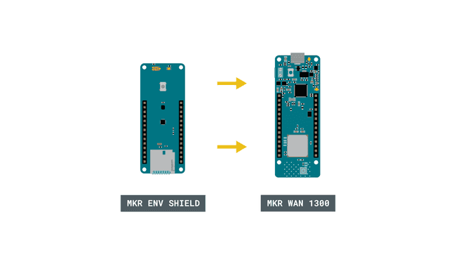
First, if we are using the MKR ENV shield, simply attach it to one of the MKR WAN 1300 boards.

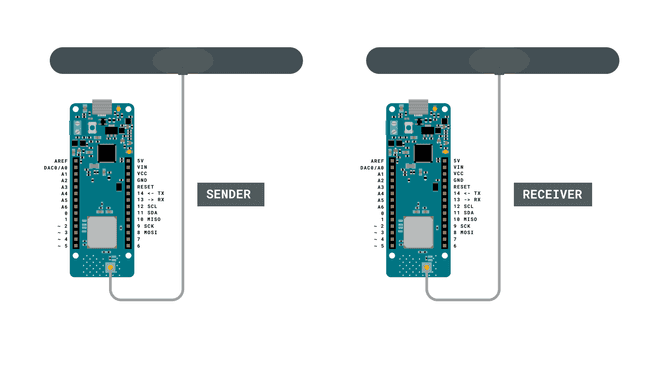
Follow the wiring diagram below to connect the antennas to the MKR WAN 1300 boards.

Let's Start
In this tutorial, we will use the MKR WAN 1300 board and the LoRa library to create a simple one way communication. It will teach you how to set up one board to be a sender and one board to be a receiver, and how to set up communication between these two without using any external services. We will learn how to send packages using the LoRa library, and how to receive packages.
All data received is printed in the Serial Monitor using a very simple interface.
To create the sender sketch, we will have to go through the following steps:
- Initialize the SPI, LoRa and Arduino_MKRENV libraries.
- Create a counter variable.
- Set the radio frequency to 868E6 (Europe) or 915E6 (North America).
- Read temperature from the MKR ENV shield.
- Begin a packet, print temperature variable to it.
- End packet.
- Increase counter each loop and print it in Serial Monitor.
To create the receiver sketch, we will have to go through the following steps:
- Initialize the SPI and LoRa libraries.
- Set the radio frequency to 868E6 (Europe) or 915E6 (North America).
- Create a function to parse incoming packet.
- Print the incoming messages.
Code Explanation
We are going to program two separate MKR WAN 1300's in this tutorial. We will start with the sender device and later on, we will create a sketch for the receiver device.
Programming the Sender
The initialization is quick and easy: we will include the SPI, LoRa and Arduino_MKRENV libraries, and create a counter variable.
1#include <Arduino_MKRENV.h>2#include <SPI.h>3#include <LoRa.h>4
5int counter = 0;In the
setup()while(!Serial);We will then initialize the LoRa library, where we will set the radio frequency to 868E6, which is used in Europe for LoRa® communication. If we are located in North America, we need to change this to 915E6.
As we are using the MKR ENV shield, we also need to initialize the Arduino_MKRENV library by using the line
if (!ENV.begin())Note: If you are using another sensor, there is no need to include the Arduino_MKRENV library, or initialize it.
1void setup() {2 Serial.begin(9600);3 while (!Serial);4 Serial.println("LoRa Sender");5
6 if (!LoRa.begin(868E6)) {7 Serial.println("Starting LoRa failed!");8 while (1);9 }10
11delay(1000);12
13 if (!ENV.begin()) {14 Serial.println("Failed to initialize MKR ENV shield!");15 while (1);16 }17}In the
loop()counterdouble temperature = ENV.readTemperature();We then begin a packet by using the command,
LoRa.beginPacket()LoRa.print()LoRa.endPacket()Finally, we add increase counter by 1 each time the loop has run, and a delay of 5 seconds, to limit the message rate. This will print in the Serial Monitor, to keep track on how many transmissions we have made.
1void loop() {2 Serial.print("Sending packet: ");3 Serial.println(counter);4
5 double temperature = ENV.readTemperature();6
7 // send packet8 LoRa.beginPacket();9 LoRa.print(temperature);10 LoRa.print(" celsius");11 LoRa.endPacket();12 counter++;13 delay(5000);14}Programming the Receiver
The initialization and setup of the receiver is more or less identical to the sender sketch, but as we are writing this sketch to only receive data, we can remove the Arduino_MKRENV library.
Inside the loop, we will not be creating any packets. Instead, we will listen to incoming ones. This is done by first using the command
int packetSize = LoRa.parsePacket();1#include <SPI.h>2#include <LoRa.h>3
4void setup() {5 Serial.begin(9600);6 while (!Serial);7
8 Serial.println("LoRa Receiver");9
10 if (!LoRa.begin(868E6)) {11 Serial.println("Starting LoRa failed!");12 while (1);13 }14}15
16void loop() {17 // try to parse packet18 int packetSize = LoRa.parsePacket();19 if (packetSize) {20 // received a packet21 Serial.print("Received packet '");22
23 // read packet24 while (LoRa.available()) {25 Serial.print((char)LoRa.read());26 }27
28 // print RSSI of packet29 Serial.print("' with RSSI ");30 Serial.println(LoRa.packetRssi());31 }32}Complete Code
If you choose to skip the code building section, the complete code can be found below:
Sender Code
1#include <Arduino_MKRENV.h>2#include <SPI.h>3#include <LoRa.h>4
5int counter = 0;6
7void setup() {8 Serial.begin(9600);9 while (!Serial);10 Serial.println("LoRa Sender");11
12 if (!LoRa.begin(868E6)) {13 Serial.println("Starting LoRa failed!");14 while (1);15 }16
17delay(1000);18
19 if (!ENV.begin()) {20 Serial.println("Failed to initialize MKR ENV shield!");21 while (1);22 }23}24
25void loop() {26 Serial.print("Sending packet: ");27 Serial.println(counter);28 double temperature = ENV.readTemperature();29 // send packet30 LoRa.beginPacket();31 LoRa.print(temperature);32 LoRa.print(" celsius");33 LoRa.endPacket();34 counter++;35 delay(5000);36}Receiver Code
1#include <SPI.h>2#include <LoRa.h>3
4void setup() {5 Serial.begin(9600);6 while (!Serial);7
8 Serial.println("LoRa Receiver");9
10 if (!LoRa.begin(868E6)) {11 Serial.println("Starting LoRa failed!");12 while (1);13 }14}15
16void loop() {17 // try to parse packet18 int packetSize = LoRa.parsePacket();19 if (packetSize) {20 // received a packet21 Serial.print("Received packet '");22
23 // read packet24 while (LoRa.available()) {25 Serial.print((char)LoRa.read());26 }27
28 // print RSSI of packet29 Serial.print("' with RSSI ");30 Serial.println(LoRa.packetRssi());31 }32}{/ Here we explain how to test the program /}
Upload Sketch and Testing the Program
Once we are finished with the coding, we can upload the sketches to each board. The easiest way to go forward is to have two separate computers, as we will need to have the Serial Monitor open for both boards. Alternatively, we can use a Serial interfacing program called Putty. But for demonstration, it is good to use two computers. This way, you can move the boards further away from each other while testing the signal.
Sending Values
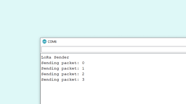
After we have uploaded the code to the sender, we need to open the Serial Monitor to initialize the program. If everything is working, it will start printing the message "Sending packet: x", where x represents the number of times the packet has been sent.

Receiving Values
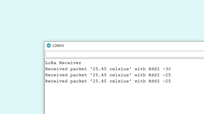
After we have uploaded the code to the receiver, we need to open the Serial Monitor to initialize the program. If everything works, we should now pick up the package we sent from the other device. The package contains the temperature, followed by RSSI (Received Signal Strength Indication). The closer this value is to 0, the stronger the signal are.

Experimenting with This Setup
Now that we have communication between the boards, we can do a simple test with the signal. If we move the sender device away from the receiver device, we will start noticing changes in the RSSI. For example, while conducting this test, the sender device was moved around 20 meters away from the receiver, which decreased the RSSI to about -60.
Troubleshoot
If the code is not working, there are some common issues we might need to troubleshoot:
- Antenna is not connected properly.
- The radio frequency is wrong. Remember, 868E6 for Europe and 915E6 for Australia & North America.
- We have not opened the Serial Monitor.
- We are using the same computer for both boards without a serial interfacing program.
Conclusion
This tutorial demonstrates a simple communication between two MKR WAN 1300 boards and a MKR ENV shield, using LoRa® technology.
Suggest changes
The content on docs.arduino.cc is facilitated through a public GitHub repository. If you see anything wrong, you can edit this page here.
License
The Arduino documentation is licensed under the Creative Commons Attribution-Share Alike 4.0 license.