LoRa® Message Service with MKR WAN 1300
Learn how to use the Serial Monitor to send messages between two MKR WAN 1300 boards using LoRa® technology.
In this tutorial, we will use two MKR WAN 1300's to set up a simple message service over the LoRa® network. This communication will be achieved through the Serial Monitor, where you can send and receive messages directly.
We will use the LoRa library to for the communication, and we will not use any external services. Additionally, we will also create specific addresses for each board. This will help ensure that the messages that we send and receive are only displayed on the corresponding devices.
Special thanks to Sandeep Mistry for creating the LoRa library.
Hardware & Software Needed
- 2x Arduino MKR WAN 1300.
- 2x Antenna.
- 2x Micro USB cable .
- 2x Computers.
- Arduino IDE (offline and online versions available).
- Arduino SAMD Board Package installed (follow this link for instructions).
- LoRa library installed (see the github repository).
Circuit
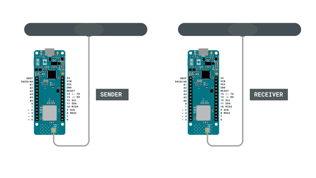
Follow the wiring diagrams below to create the circuits for the sender and receiver boards.

Let's Start
In this tutorial, we will create a message service that utilizes the LoRa® network. In our other tutorials for the MKR WAN 1300 board, we have typically set up one board as a sender, and one as a receiver. Now, we will instead set them up as both sender and receiver. This will allow us to both send and receive packets simultaneously, which works very similar to any messenger service you might be used to!
To do this, we basically only need to create one sketch that we will upload to each of the MKR WAN 1300 boards, with only some minor adjustments made in the code for each.
In the code, we will have to do the following to make it work:
- Initialize the SPI and LoRa libraries.
- Create a string to store outgoing messages.
- Create two bytes: one for local address, one for the destination address.
- Set the radio frequency to 868E6 (Europe) or 915E6 (North America).
- Create a while loop to read input from the Serial Monitor.
- After input is read, create and send a LoRa® packet to destination address.
- Continuously listen for incoming LoRa® packets.
- If a packet comes in that matches the local address, parse it and print it in the Serial Monitor.
- Print the signal strength (RSSI) each time a packet comes in.
Code Explanation
We are going to program two separate MKR WAN 1300's in this tutorial. The sketches are 99% identical, but there are two major things that will differ: the
localAddressdestinationThe table below provides a better explanation to this:
| Name | Local Address | Destination Address |
|---|---|---|
| Peter | 0xBB | 0xFF |
| Juan | 0xFF | 0xBB |
{/ This table above is not rendered properly /}
Note: This section is optional and only explains the code. To find the full version of the code, you can find it below this section.
Programming First Device (Peter)
In the initialization we will include the SPI and LoRa libraries. We will also create a string named
messageWe will also create two bytes:
localAddressdestination0xFF0xBBImportant: these addresses need to be switched on the sketches we upload to the board.
1#include <SPI.h>2#include <LoRa.h>3
4String message;5
6byte localAddress = 0xBB;7byte destination = 0xFF;In the
setup()1void setup() {2 Serial.begin(9600);3 Serial.println("LoRa message service");4 if (!LoRa.begin(868E6)) {5 Serial.println("Starting LoRa failed!");6 while (1);7 }8 delay(1000);9}In the
loop()messageThen, as the message is entered, we exit the while loop and go to a conditional. If the message is longer than 0 characters, we print
"Peter: "messagedestinationlocalAddressLoRa.endpacket()messageNow we also want to receive packets. This is done by calling the function
onReceive(LoRa.parsePacket());1void loop() {2 while (Serial.available()) {3 delay(2); //delay to allow byte to arrive in input buffer4 char c = Serial.read();5 message += c;6 }7
8 if (message.length() > 0) {9 Serial.println("Peter: " + message); //name seen in the Serial Monitor10 LoRa.beginPacket();11 LoRa.write(destination);12 LoRa.write(localAddress);13 LoRa.print("Peter: " + message); //name seen on the receiving end14 LoRa.endPacket();15 message = "";16 }17
18 onReceive(LoRa.parsePacket());19
20}Whenever the
onReceive()But if a packet comes in, there are two major things that happen. First, we read the packet, using the command
int recipient = LoRa.read();localAddressincomingWe then compare
recipientlocalAddress0xFFFinally, we print the message stored in the
incoming1void onReceive(int packetSize) {2 if (packetSize == 0) return; // if there's no packet, return3
4 int recipient = LoRa.read();5 String incoming = "";6
7 while (LoRa.available()) {8 incoming += (char)LoRa.read();9 }10
11 if (recipient != localAddress && recipient != 0xFF) {12 Serial.println("This message is not for me.");13 return; // skip rest of function14 }15
16 Serial.print(incoming);17 Serial.print(" || RSSI: ");18 Serial.println(LoRa.packetRssi());19 Serial.println();20}Programming Second Device (Juan)
As mentioned earlier, the code is almost identical for both devices. The only difference is that we will switch the address in the initialization, and the name printed in the Serial Monitor.
1#include <SPI.h>2#include <LoRa.h>3
4String message;5
6byte localAddress = 0xFF;7byte destination = 0xBB;8
9void setup() {10 Serial.begin(9600);11 Serial.println("LoRa message service");12 if (!LoRa.begin(868E6)) {13 Serial.println("Starting LoRa failed!");14 while (1);15 }16 delay(1000);17}18void loop() {19 while (Serial.available()) {20 delay(2); //delay to allow byte to arrive in input buffer21 char c = Serial.read();22 message += c;23 }24
25 if (message.length() > 0) {26 Serial.println("Juan: " + message); //name seen in Serial Monitor27 LoRa.beginPacket();28 LoRa.write(destination);29 LoRa.write(localAddress);30 LoRa.print("Juan: " + message); //name seen on the receiving end31 LoRa.endPacket();32 message = "";33 }34
35 onReceive(LoRa.parsePacket());36
37}38
39
40void onReceive(int packetSize) {41 if (packetSize == 0) return; // if there's no packet, return42
43 int recipient = LoRa.read();44 String incoming = "";45
46 while (LoRa.available()) {47 incoming += (char)LoRa.read();48 }49
50 if (recipient != localAddress && recipient != 0xBB) {51 Serial.println("This message is not for me.");52 return; // skip rest of function53 }54
55 Serial.print(incoming);56 Serial.print(" || RSSI: ");57 Serial.println(LoRa.packetRssi());58 Serial.println();59}Complete Code
If you choose to skip the code building section, the complete code can be found below:
Device #1 Full Code
1#include <SPI.h>2#include <LoRa.h>3
4int counter = 0;5int button = 2;6int buttonState;7
8void setup() {9 pinMode(button, INPUT_PULLUP);10
11 Serial.begin(9600);12
13 while (!Serial);14 Serial.println("LoRa Sender");15
16 if (!LoRa.begin(868E6)) {17 Serial.println("Starting LoRa failed!");18 while (1);19 }20 delay(1000);21}22
23void loop() {24 buttonState = digitalRead(button);25
26 if (buttonState == LOW) {27 // send packet28 LoRa.beginPacket();29 LoRa.print("button pressed");30 LoRa.endPacket();31 counter++;32 Serial.print("Sending packet: ");33 Serial.println(counter);34 delay(500);35 }36}Device #2 Full Code
1#include <SPI.h>2#include <LoRa.h>3
4String contents = "";5String buttonPress = "button pressed";6bool x;7
8int led = 2;9
10void setup() {11
12 pinMode(led, OUTPUT);13 Serial.begin(9600);14 while (!Serial);15 //Wire.begin();16 Serial.println("LoRa Receiver");17
18 if (!LoRa.begin(868E6)) {19 Serial.println("Starting LoRa failed!");20 while (1);21 }22}23
24void loop() {25 // try to parse packet26 int packetSize = LoRa.parsePacket();27 if (packetSize) {28 // received a packet29 Serial.print("Received packet '");30
31 // read packet32 while (LoRa.available()) {33 contents += (char)LoRa.read();34 }35
36 // print RSSI of packet37 Serial.print("' with RSSI ");38 Serial.println(LoRa.packetRssi());39 Serial.println(contents);40
41 if(contents.equals(buttonPress)){42 x = !x;43 }44
45 if(x == true) {46 digitalWrite(led, HIGH);47 Serial.println("led on");48 }49 else {50 digitalWrite(led, LOW);51 Serial.println("led off");52 }53
54 contents = "";55 }56}Upload Sketch and Testing the Program
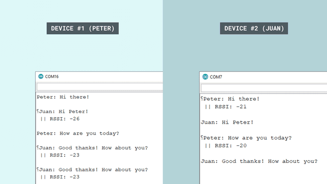
Once we are finished with the code, we can upload the sketches to each board. At this point, we will need two computers, as we are going to write messages between them. When the code has been uploaded, open the Serial Monitor on each computer.
If everything goes right, we should be able to write messages over the LoRa® network. This is done by simply typing a message in the Serial Monitor of either device, and hit "enter" once finished. This will store the entered message in a string called
messagemessageImportant: the Serial Monitor needs to be open for both devices in order to send and receive messages. If we send a message from Device #1, we will need to have the Serial Monitor open on Device #2.
We should now receive the message in Device #2, along with the RSSI and the name of the sender. As chosen in this tutorial, the name for Device #1 is Peter and for Device #2, the name is Juan.

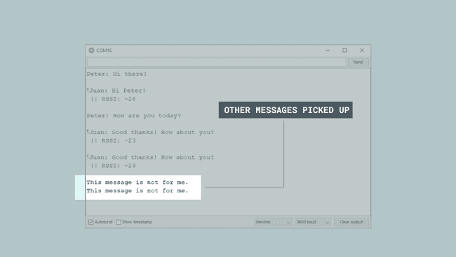
It also happens that we pick up messages that were not intended for us. Earlier in the sketch, inside the
receive()1if (recipient != localAddress && recipient != 0xBB) {2 Serial.println("This message is not for me.");3 return;4 }And this is how it looks like in the Serial Monitor:

Troubleshoot
If the code is not working, there are some common issues we might need to troubleshoot:
- Antenna is not connected properly.
- The radio frequency is wrong. Remember, 868E6 for Europe and 915E6 for Australia & North America.
- We have not opened the Serial Monitor.
- We are using the same computer for both boards without a serial interfacing program.
Conclusion
In this tutorial, we have created a messaging over LoRa® application, using two MKR WAN 1300 boards and two antennas. In the right conditions, these boards can send messages over very long distances, and can be an ideal solution for remote places where internet access is limited.
Suggest changes
The content on docs.arduino.cc is facilitated through a public GitHub repository. If you see anything wrong, you can edit this page here.
License
The Arduino documentation is licensed under the Creative Commons Attribution-Share Alike 4.0 license.