Proximity Detection with Arduino Nicla Vision
Learn how to use the proximity sensor to vary the speed of the LED's blink.
Overview
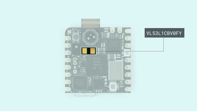
In this tutorial you will use the Nicla Vision to detect proximity, thanks to the Time of Flight (ToF) sensor VL53L1X.
This tutorial teaches you how to create a sketch that will blink the built-in RGB LED and control the speed of its blink with the proximity values. It can be useful for future projects where there is the need to control the camera only when something is detected in front of the sensor.
Goals
- Set up the needed libraries
- Learn how to interact with the proximity readings
- Change the RGB values of the LED
Required Hardware and Software
- Nicla Vision
- VL53L1X library (Available in the Library Manager)
Instructions
Time of Flight Sensor

To make sure that the sketch works properly, the latest versions of the Arduino Mbed OS Nicla core and the VL53L1X library need to be installed. Both can be found inside the Arduino IDE.
- The Arduino Mbed OS Nicla core can be found in the boards manager...
- The VL53L1X library can be found in the Library manager
If you are using version 2.2.0 or later of the Arduino IDE, install the VL53L1X library as follows:
- In the left bar of the Arduino IDE, click on the Library Manager.
- Search for VL53L1X.
- Click the VL53L1X entry in the list, authored by Pololu.
- Click Install. More detailed instructions on how to install a library can be found here.
Include the Needed Libraries and Objects Declaration
First of all, declare the sensor's class so you can access it later on in your sketch. You can use variables to control the time elements in the sketch. This will make sure that the readings stay accurate over time.
1#include "VL53L1X.h"2VL53L1X proximity;3
4bool blinkState = false;5int reading = 0;6int timeStart = 0;7int blinkTime = 2000;Initialize the Proximity Sensor and the LED
Inside the setup you need to initialize and configure the proximity sensor. Also, the RGB LED needs to be set as an output to make it light up and enable you to change its behavior.
The LEDs are accessed in the same way as on the Portenta H7: LEDR, LEDG and LEDB.
1void setup(){2 Serial.begin(115200);3 Wire1.begin();4 Wire1.setClock(400000); // use 400 kHz I2C5 proximity.setBus(&Wire1);6 7 pinMode(LEDB,OUTPUT);8 digitalWrite(LEDB, blinkState);9 10 if (!proximity.init()){11 Serial.println("Failed to detect and initialize sensor!");12 while (1);13 }14
15 proximity.setDistanceMode(VL53L1X::Long);16 proximity.setMeasurementTimingBudget(10000);17 proximity.startContinuous(10);18 }Make sure you initialize
, set the clock speed to 400 kHz and set the bus pointer to Wire1
. It will not work if you do not add these settings.Wire1
Control the Speed of the Blink
The sketch is going to get the reading on every loop, store it and then the state of the LED will change until the time is up and another proximity reading is taken.
1void loop(){2 reading = proximity.read();3 Serial.println(reading);4
5 if (millis() - timeStart >= reading){6 digitalWrite(LEDB, blinkState);7 timeStart = millis();8
9 blinkState = !blinkState;10 }11 }Complete Sketch
1#include "VL53L1X.h"2VL53L1X proximity;3
4bool blinkState = false;5int reading = 0;6int timeStart = 0;7int blinkTime = 2000;8
9void setup() {10 Serial.begin(115200);11 Wire1.begin();12 Wire1.setClock(400000); // use 400 kHz I2C13 proximity.setBus(&Wire1);14
15
16 pinMode(LEDB, OUTPUT);17 digitalWrite(LEDB, blinkState);18
19 if (!proximity.init()) {20 Serial.println("Failed to detect and initialize sensor!");21 while (1);22 }23
24 proximity.setDistanceMode(VL53L1X::Long);25 proximity.setMeasurementTimingBudget(10000);26 proximity.startContinuous(10);27}28
29void loop() {30 reading = proximity.read();31 Serial.println(reading);32
33 if (millis() - timeStart >= reading) {34 digitalWrite(LEDB, blinkState);35 timeStart = millis();36
37 blinkState = !blinkState;38 }39}Here is a demo video of the example running on the Nicla Vision:
API
| Command | Details | type |
|---|---|---|
| setAddress(newAddress) | Change the I2C sensor's address (Mandatory to set it to | |
| getAddress() | Get the Sensor's I2C address | |
| init() | Configures the sensor and needed data. Like the usual begin() | |
| setDistanceMode(mode) | Set the distance mode (check the datasheet). Available modes | |
| getDistanceMode() | Returns the mode that has been set. Available modes | |
| setMeasurementTimingBudget(uSeconds) | Set the time to get the measure, greater the value, better precision. In micro seconds. | |
| getMeasurementTimingBudget() | Get the measure timing value in micro seconds. | |
| startContinuous() | Start the non stop readings, set the period inside the parameter, after that time you will get the reading. | |
| stopContinuous() | Stop the non stop measurements. | |
| read() | Get the last reading from the continuous mode. | |
| readSingle() | Trigger one reading and get its result. | |
| dataReady() | Returns if the sensor has new data available. | |
| setTimeout(mSeconds) | Configure the milliseconds the sensor will wait in case it is not getting the proper reading to abort, and continue with a new one, 0 disables it. | |
| getTimeout() | Get the configured timeout value. | |
| timeoutOccurred() | Returns true whenever the sensor had a timeout. | |
Conclusion
In this tutorial we went through how to get readings from the ToF sensor and how to use these readings to change how the built-in LED behaves. At the end of the tutorial you can also find a reference list for the ToF library.
Suggest changes
The content on docs.arduino.cc is facilitated through a public GitHub repository. If you see anything wrong, you can edit this page here.
License
The Arduino documentation is licensed under the Creative Commons Attribution-Share Alike 4.0 license.