GIGA R1 Camera Guide
Learn about the GIGA R1 WiFi's camera connector, and how to use existing examples.
The GIGA R1 has a dedicated camera connector that allows certain camera modules to mount directly on the board. This makes it possible to add machine vision to your GIGA R1 board without much effort at all.
In this guide, we will explore the following:
- Where the camera connector is located.
- What cameras are compatible.
- What library to use.
- How to setup a camera stream to a processing application.
Hardware & Software Needed
To follow and use the examples provided in this guide, you will need an Arduino GIGA R1 WiFi
You will also need the following software:
- Arduino IDE (any version).
- Processing (for displaying camera feed).
Supported Cameras
The GIGA R1 currently supports the following cameras, via the Camera library that is bundled with the Arduino Mbed PS GIGA Board Package:
- OV7670 and OV7675
- GC2145
- Himax HM01B0
- Himax HM0360
Camera Connector
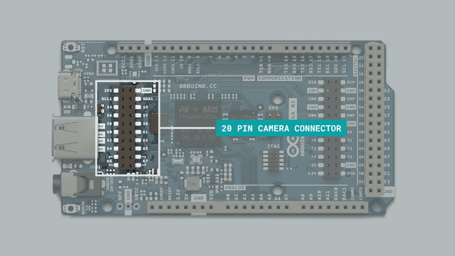
The 20 pin camera connector onboard the GIGA R1 is designed to be directly compatible with some breakout boards from ArduCam.
This allows you to simply connect the camera module directly to the board, without making any additional circuit.
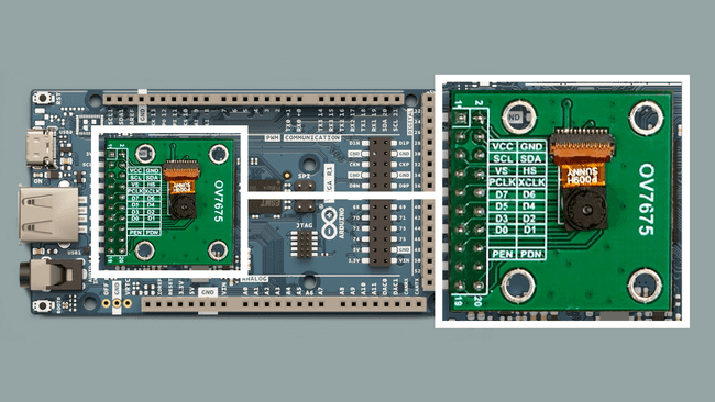
Some of the 20 pin connector breakout boards from ArduCam can be found here.
The complete pin map can be found below:
| Left | Right |
|---|---|
| 3V3 | GND |
| SCL1 | SDA1 |
| 54 | 55 |
| 56 | 57 |
| 58 | 59 |
| 60 | 61 |
| 62 | 63 |
| 64 | 65 |
| 66 | 67 |
| 66 | 67 |
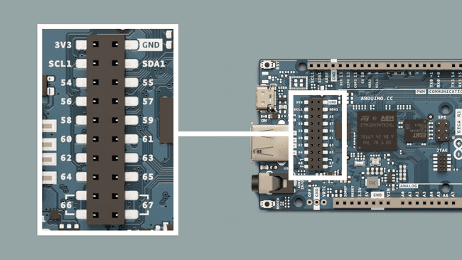
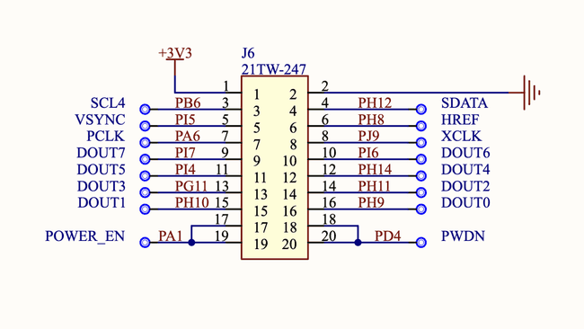
You can also view the schematic for this connector in more detail just below. This is useful to understand exactly which pins on the STM32H747XI microcontroller is used.
Raw Bytes Over Serial (Processing)
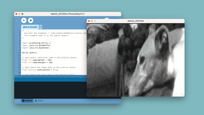
This example allows you to stream the sensor data from your camera to a Processing application, using serial over USB. This will allow you to see the image directly in your computer.
This example requires a version of Processing on your machine.
Step 1: Arduino
Upload the following sketch to your board.
This sketch is also available in the Arduino IDE via Examples > Camera > CameraCaptureRawBytes.
1#include "camera.h"2
3#ifdef ARDUINO_NICLA_VISION4 #include "gc2145.h"5 GC2145 galaxyCore;6 Camera cam(galaxyCore);7 #define IMAGE_MODE CAMERA_RGB5658#elif defined(ARDUINO_PORTENTA_H7_M7)9 #include "hm0360.h"10 HM0360 himax;11 Camera cam(himax);12 #define IMAGE_MODE CAMERA_GRAYSCALE13#elif defined(ARDUINO_GIGA)14 #include "ov7670.h"15 OV7670 ov7670;16 Camera cam(ov7670);17 #define IMAGE_MODE CAMERA_RGB56518#else19#error "This board is unsupported."20#endif21
22/*23Other buffer instantiation options:24 FrameBuffer fb(0x30000000);25 FrameBuffer fb(320,240,2);26*/27FrameBuffer fb;28
29unsigned long lastUpdate = 0;30
31
32void blinkLED(uint32_t count = 0xFFFFFFFF)33{34 pinMode(LED_BUILTIN, OUTPUT);35 while (count--) {36 digitalWrite(LED_BUILTIN, LOW); // turn the LED on (HIGH is the voltage level)37 delay(50); // wait for a second38 digitalWrite(LED_BUILTIN, HIGH); // turn the LED off by making the voltage LOW39 delay(50); // wait for a second40 }41}42
43void setup() {44 // Init the cam QVGA, 30FPS45 if (!cam.begin(CAMERA_R320x240, IMAGE_MODE, 30)) {46 blinkLED();47 }48
49 blinkLED(5);50}51
52void loop() {53 if(!Serial) { 54 Serial.begin(921600);55 while(!Serial);56 }57
58 // Time out after 2 seconds and send new data59 bool timeoutDetected = millis() - lastUpdate > 2000;60 61 // Wait for sync byte.62 if(!timeoutDetected && Serial.read() != 1) return; 63
64 lastUpdate = millis();65 66 // Grab frame and write to serial67 if (cam.grabFrame(fb, 3000) == 0) {68 Serial.write(fb.getBuffer(), cam.frameSize());69 } else {70 blinkLED(20);71 }72}Step 2: Processing
The following Processing sketch will launch a Java app that allows you to view the camera feed. As data is streamed via serial, make sure you close the Serial Monitor during this process, else it will not work.
Important! Make sure to replace the following line in the code below:
, with the name of your port./dev/cu.usbmodem14301
Click on the "PLAY" button to initialize the app.
1/*2 Use with the Examples -> CameraCaptureRawBytes Arduino sketch.3 This example code is in the public domain.4*/5
6import processing.serial.*;7import java.nio.ByteBuffer;8import java.nio.ByteOrder;9
10Serial myPort;11
12// must match resolution used in the Arduino sketch13final int cameraWidth = 320;14final int cameraHeight = 240;15
16// Must match the image mode in the Arduino sketch17final boolean useGrayScale = true;18
19// Must match the baud rate in the Arduino sketch20final int baudRate = 921600;21
22final int cameraBytesPerPixel = useGrayScale ? 1 : 2;23final int cameraPixelCount = cameraWidth * cameraHeight;24final int bytesPerFrame = cameraPixelCount * cameraBytesPerPixel;25final int timeout = int((bytesPerFrame / float(baudRate / 10)) * 1000 * 2); // Twice the transfer rate26
27PImage myImage;28byte[] frameBuffer = new byte[bytesPerFrame];29int lastUpdate = 0;30boolean shouldRedraw = false;31
32void setup() {33 size(640, 480); 34
35 // If you have only ONE serial port active you may use this:36 //myPort = new Serial(this, Serial.list()[0], baudRate); // if you have only ONE serial port active37
38 // If you know the serial port name39 //myPort = new Serial(this, "COM5", baudRate); // Windows40 //myPort = new Serial(this, "/dev/ttyACM0", baudRate); // Linux41 myPort = new Serial(this, "/dev/cu.usbmodem14301", baudRate); // Mac42
43 // wait for a full frame of bytes44 myPort.buffer(bytesPerFrame); 45
46 myImage = createImage(cameraWidth, cameraHeight, ALPHA);47 48 // Let the Arduino sketch know we're ready to receive data49 myPort.write(1);50}51
52void draw() {53 // Time out after a few seconds and ask for new data54 if(millis() - lastUpdate > timeout) {55 println("Connection timed out."); 56 myPort.clear();57 myPort.write(1);58 }59 60 if(shouldRedraw){ 61 PImage img = myImage.copy();62 img.resize(640, 480);63 image(img, 0, 0);64 shouldRedraw = false;65 }66}67
68int[] convertRGB565ToRGB888(short pixelValue){ 69 //RGB56570 int r = (pixelValue >> (6+5)) & 0x01F;71 int g = (pixelValue >> 5) & 0x03F;72 int b = (pixelValue) & 0x01F;73 //RGB888 - amplify74 r <<= 3;75 g <<= 2;76 b <<= 3; 77 return new int[]{r,g,b};78}79
80void serialEvent(Serial myPort) { 81 lastUpdate = millis();82 83 // read the received bytes84 myPort.readBytes(frameBuffer);85
86 // Access raw bytes via byte buffer 87 ByteBuffer bb = ByteBuffer.wrap(frameBuffer);88 89 // Ensure proper endianness of the data for > 8 bit values.90 // The 1 byte bb.get() function will always return the bytes in the correct order.91 bb.order(ByteOrder.BIG_ENDIAN);92
93 int i = 0;94
95 while (bb.hasRemaining()) {96 if(useGrayScale){97 // read 8-bit pixel data98 byte pixelValue = bb.get();99
100 // set pixel color101 myImage.pixels[i++] = color(Byte.toUnsignedInt(pixelValue));102 } else {103 // read 16-bit pixel data104 int[] rgbValues = convertRGB565ToRGB888(bb.getShort());105
106 // set pixel RGB color107 myImage.pixels[i++] = color(rgbValues[0], rgbValues[1], rgbValues[2]);108 } 109 }110 111 myImage.updatePixels();112 113 // Ensures that the new image data is drawn in the next draw loop114 shouldRedraw = true;115 116 // Let the Arduino sketch know we received all pixels117 // and are ready for the next frame118 myPort.write(1);119}If all goes well, you should now be able to see the camera feed.
Summary
In this article, we learned a bit more about the camera connector on board the GIGA R1 board, how it is connected to the STM32H747XI microcontroller, and a simple example on how to connect an inexpensive OV7675 camera module to a Processing application.
Suggest changes
The content on docs.arduino.cc is facilitated through a public GitHub repository. If you see anything wrong, you can edit this page here.
License
The Arduino documentation is licensed under the Creative Commons Attribution-Share Alike 4.0 license.