Arduino GIGA R1 Cheat Sheet
Learn how to set up the GIGA R1, get a quick overview of the components, information regarding pins and how to use different Serial (SPI, I2C, UART), and much, much more.
The Arduino GIGA R1 is one of our most feature-packed Arduino boards to date, supported by the same powerful, ML-capable, dual-core microcontroller found in the Pro family's Portenta H7. It features support for display connectors, USB-host, an Audio Jack, an Arducam connector, a CAN bus, 4 UART Serial Ports, 2 I2C buses, dedicated DAC Pins, and much, much more.
This article is a collection of resources and guides to make use of every great feature of this powerful hardware.
You can also visit the documentation platform for the GIGA R1.
Datasheet
The full datasheet is available as a downloadable PDF from the link below:
Arduino Cloud
The GIGA R1 WiFi is compatible with the Arduino Cloud, a Cloud service that allows you to create IoT applications in just minutes.
Visit the Getting Started with Arduino Cloud guide for more information.
Power Supply
To power the GIGA R1 you may either use a USB-C cable, or the VIN pin.
If you're using the USB-C connector you must power it with 5V.
Powering the board with the VIN pin gives you more options, as you can safely power the board with any voltage between 6-24V.
By connecting the OFF pin to GND you can cut the power supply to the board, turning it off completely. Read more about this feature in the OFF-pin section of this article
It should however be noted that the internal operating voltage of the microcontroller is 3.3V, and you should not apply voltages higher than that to the GPIO pins.
Installation
For detailed instructions on how to install the GIGA R1 Board Package, please refer to the Getting Started with GIGA R1 guide.
The GIGA R1 can be programmed through:
- The Classic Arduino IDE 1.8.X,
- the Arduino IDE 2,
- and the Web-editor.
Board Package
The GIGA R1 is based on the Arduino Mbed OS GIGA Board Package, which also provides a set of examples that works out of the box.
These examples are available in the Arduino IDE via File > Examples > Examples for GIGA.
Mbed OS
As the Arduino Mbed OS GIGA Board Package is based on MbedOS, it is possible for the operating system to crash while running a sketch.
On most Arduino boards, when a sketch fails due to e.g. memory shortage, the board resets.
On the GIGA R1, whenever the MbedOS fails, the board does not reset automatically. Instead, if it fails, the onboard red LED will start to blink in a looping pattern of 4 fast blinks and 4 slow blinks.
Please note, the red LED does NOT mean your board is broken or bricked.
In case you encounter the red LED, you can either:
- Press the reset button once (this resets the sketch).
- Double-tap the reset button to enter bootloader mode (allowing you to re-program the board).
Boot0
Pressing and holding the button labelled
BOOT0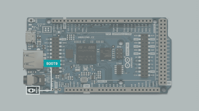
The state of this button can also be read from a sketch while it is running, giving you a basic interactive component without needing to do any wiring.
To read the state of the Boot0 button in your sketch, you use this line of code:
1digitalRead(PC_13);STM32H747XI Microcontroller
The GIGA R1 features the powerful dual core STM32H747XI microcontroller found on the Arduino PRO family's Portenta H7 board, but in a form factor accessible to any maker who has tinkered with an Arduino board before.
The STM32H747XI is a powerful dual core chip, capable of being programmed with a high-level language such as MicroPython on one core, while simultaneously running Arduino compiled code on the other, and having the two programs communicate with each other seamlessly.
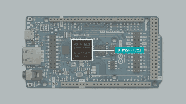
The microcontroller operates on a voltage of 3.3V, applying a higher voltage than that, such as 5V, to a pin might damage the microcontroller.
Memory
RAM
The GIGA R1 has 1 MB of SRAM that is internal to the processor, and 8MB of SDRAM which you can access and write to.
To access the SDRAM you need to use the SDRAM library, include it in your sketch with:
1#include "SDRAM.h"Before writing to the SDRAM, you need to allocate it, the following code will create an array that reserves 7MB of the SDRAM for you to write to.
1uint8_t* myVeryBigArray = (uint8_t*)SDRAM.malloc(7 * 1024 * 1024);If you now store any data in this array, it will be written to SDRAM.
1for (int i = 0; i<128; i++) {2 myVeryBigArray[i] = i;3 }When you no longer need to use the SDRAM, you can free it, so it can be used for other things.
1SDRAM.free(myVeryBigArray);Flash
The GIGA R1 has 2MB of internal, and 16MB of external Flash storage. The external Flash storage on the GIGA R1 is QSPI and can be accessed and used to store data. If you need to, you can configure the board to act as a USB flash drive, so you can store files such as images, audio, and more.
The GIGA firmware has full support for FATFS and littleFS.
To access the QSPI flash storage as a USB flash drive, you need to follow a few steps, first you need to update the WiFi modules firmware, then you need to create partitions on the flash storage, before finally exposing the partitions to be detected by a computer. These three steps are broken down into different built in example sketches that conveniently all come with the GIGA Board Package.
Firstly, navigate in the IDE menu to
File > Examples > STM32H747_System > WiFiFirmwareUpdaterIn the Serial monitor you will now be able to interface with the board. Follow the instructions by sending a "y" in the monitor. You will now see the progress of the firmware update, don't power off the board until you see a message telling you that it is safe.
After completing this, the next step is to partition the flash storage. Navigate to
File > Examples > STM32H747_System > QSPIFormatLastly, navigate to
File > Examples > USB Mass Storage > AccessFlashAsUSBDiskOnce this is completed, you should now see a new storage device connected as a portable storage device in your computer.
This can be very useful, as this flash storage does not get deleted when you upload a new sketch to the board. Meaning that you can store files on the board, and then upload a new sketch that can access and use those files without the need for an SD card and card reader.
*Note: In this configuration, the USB serial port used for serial communication with the computer is occupied, so you won't be able to send or read information in the serial monitor. This includes uploading new sketches. To upload a new sketch you need to put the GIGA R1 in DFU mode by double pressing the RST button.***
Radio Module
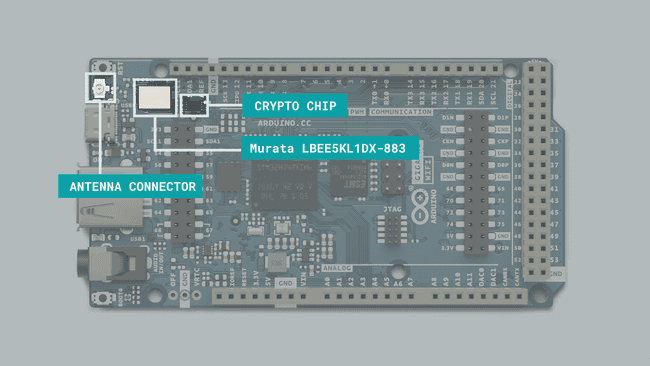
The Wi-Fi® / Bluetooth® module onboard the GIGA R1 WiFi is the Murata LBEE5KL1DX-883. This module does not come with a built-in antenna, but an external antenna is included when purchasing the board.
The antenna connector (see image above) is located right next to the USB-C connector, and is of a U.FL. type.
Wi-Fi®
Wi-Fi® on the GIGA R1 WiFi is supported via the
WiFiTo use the Wi-Fi® features on this board, please refer to the GIGA R1 WiFi Network Examples guide.
The easiest way to connect your board to the Internet is via the Arduino Cloud platform. Here you can configure, program, monitor and synchronize your devices without having to write any networking code.
Bluetooth® Low Energy
To use the BLE features on this board, refer to the ArduinoBLE library documentation.
Ethernet
If you want to add Ethernet connectivity to your project, the Arduino Ethernet Shield Rev2 is compatible. In the shield's documentation, you will find a series of examples.
Audio Jack
The GIGA R1 features an audio jack, with 2x DAC channels, and 1x ADC channel, and is capable of reading input from a microphone, as well as outputting sound through a speaker.
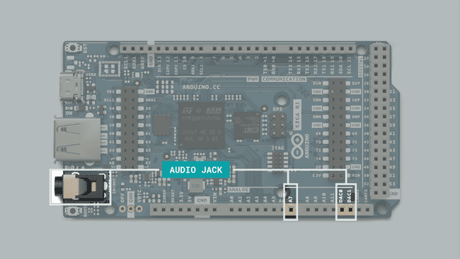
The audio jack is connected to the following pins:
- A12 / DAC0
- A13 / DAC1
- A7
Both of these come with caveats, though. As there is no amplifier circuit on the board itself, driving a high impedance speaker directly without an amplifier circuit could cause damage to the board, and microphone input without an amplifier circuit between the microphone and the board may sound dim.
In the coming sections we will provide resources and basic information on how to use the audio jack as both an input and an output.
DAC Output
In order to output audio from the DAC, you can use the
AdvancedAnalogReduxInclude the library and create the
AdvancedDACdac1(A12)void setup()1#include "AdvancedDAC.h"2
3AdvancedDAC dac1(A12);To initialize the library, and check that everything went as expected with the following piece of code:
1if (!dac1.begin(AN_RESOLUTION_12, 8000, 32, 64)) {2 Serial.println("Failed to start DAC!");3 while (1);4 }Then lastly, add the following code to
void loop()1if (dac1.available()) {2
3 // Get a free buffer for writing4 SampleBuffer buf = dac1.dequeue();5
6 // Write data to buffer7 for (int i=0; i<buf.size(); i++) {8 buf.data()[i] = (i % 2 == 0) ? 0: 0xfff;9 }10
11 // Write the buffer data to DAC12 dac1.write(buf);13 }*The options for audio playback and generation on your GIGA R1 are much more vast than this, however. To learn about audio playback in depth, check out the GIGA R1 Audio Guide.*
ADC Input
The audio jack on the GIGA R1 is also connected to pin A7, for microphone capabilities.
To take advantage of this, you can use the
AdvancedAnalogReduxAdvancedADCvoid setup()1#include "AdvancedADC.h"2
3AdvancedADC adc1(A7);Now, initialize the library and run a check to make sure everything went as expected with the following code within
void setup()1Serial.begin(9600);2
3 // Resolution, sample rate, number of samples per channel, and queue depth of the ADC4 if (!adc1.begin(AN_RESOLUTION_16, 16000, 32, 64)) {5 Serial.println("Failed to start analog acquisition!");6 while (1);7 }Finally, read the ADC, and store it in a way that you can use it, do this within
void loop()1if (adc1.available()) {2 SampleBuffer buf = adc1.read();3
4 // Print first sample5 Serial.println(buf[0]);6
7 // Release the buffer to return it to the pool8 buf.release();*The options for audio input on your GIGA R1 are much more vast than this, however. To learn about audio recording in depth, check out the GIGA R1 Audio Guide.*
MIPI DSI®
Display Serial Interface (DSI), is a specification from the Mobile Industry Processor Interface (MIPI).
The STM32H747XI has an internal 2D graphics accelerator with support for resolutions up to 1024x768, it also has the ability to encode and decode JPEG codec. This is what allows the GIGA R1 to boast a 2 lane MIPI display interface.
The GIGA Display Shield is designed to be mounted on the GIGA R1 through the MIPI/DSI connector located on the board, with support for popular frameworks such as LVGL and GFX.
The pinout for the display connector is shown in the image below:
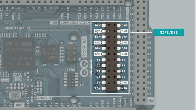
The following pins are directly connected to the STM32H747XI and cannot be used as GPIOs.
- D1N
- D1P
- CKN
- CKP
- D0N
- D0P
The following pins can also be used as GPIOs:
- D68
- D69
- D70
- D71
- D72
- D73
- D74
- D75
The connector also has a series of power connections, including:
- 3.3 V
- 5 V
- GND
- VIN
USB Features
To learn about all the USB features in more detail, visit the Guide to GIGA R1 USB Features.
USB HID
The GIGA R1 comes with support for HID, and can be used as either a keyboard or mouse. For more information, visit the USB HID section.
USBHost
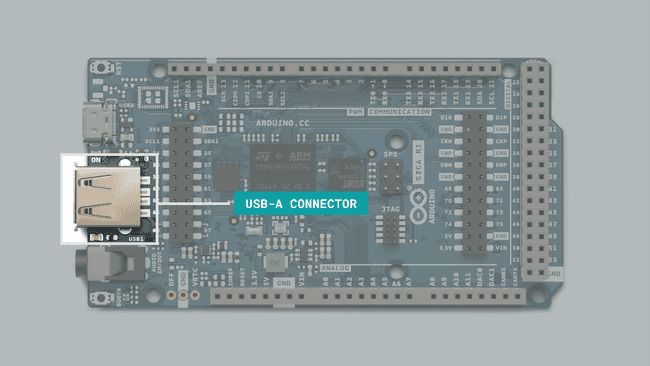
The USB-A port you find on the GIGA R1 is configured as a host-only port, meaning that it cannot be used to program the board, instead it is used to connect peripherals to the board.
The board can receive keyboard input, effectively enabling a few hundred more inputs without any wiring, or be used to read & write files on a USB flash drive, which makes it possible to for example, build a datalogger.
For more information, go to the following sections:
RTC
RTC Manual Example
The following sketch will continuously print the time in the Serial monitor.
1#include "mbed.h"2#include <mbed_mktime.h>3
4constexpr unsigned long printInterval { 1000 };5unsigned long printNow {};6
7void setup() {8 Serial.begin(9600);9 RTCset();10}11
12void loop() {13 if (millis() > printNow) {14 Serial.print("System Clock: ");15 Serial.println(getLocaltime());16 printNow = millis() + printInterval;17 }18}19
20void RTCset() // Set cpu RTC21{ 22 tm t;23 t.tm_sec = (0); // 0-5924 t.tm_min = (52); // 0-5925 t.tm_hour = (14); // 0-2326 t.tm_mday = (18); // 1-3127 t.tm_mon = (11); // 0-11 "0" = Jan, -1 28 t.tm_year = ((22)+100); // year since 1900, current year + 100 + 1900 = correct year29 set_time(mktime(&t)); // set RTC clock 30}31
32String getLocaltime()33{34 char buffer[32];35 tm t;36 _rtc_localtime(time(NULL), &t, RTC_4_YEAR_LEAP_YEAR_SUPPORT);37 strftime(buffer, 32, "%Y-%m-%d %k:%M:%S", &t);38 return String(buffer);39}To get accurate time, you'll want to change the values in
void RTCset()RTC / UDP / NTP Example
With the following sketch, you can automatically set the time by requesting the time from a Network Time Protocol (NTP), using the UDP protocol.
1/*2 Udp NTP Client3
4 Get the time from a Network Time Protocol (NTP) time server5 Demonstrates use of UDP sendPacket and ReceivePacket6 For more on NTP time servers and the messages needed to communicate with them,7 see http://en.wikipedia.org/wiki/Network_Time_Protocol8
9 created 4 Sep 201010 by Michael Margolis11 modified 9 Apr 201212 by Tom Igoe13 modified 28 Dec 202214 by Giampaolo Mancini15
16This code is in the public domain.17 */18
19#include <WiFi.h>20#include <WiFiUdp.h>21#include <mbed_mktime.h>22
23int status = WL_IDLE_STATUS;24#include "arduino_secrets.h"25///////please enter your sensitive data in the Secret tab/arduino_secrets.h26char ssid[] = ""; // your network SSID (name)27char pass[] = ""; // your network password (use for WPA, or use as key for WEP)28int keyIndex = 0; // your network key index number (needed only for WEP)29
30unsigned int localPort = 2390; // local port to listen for UDP packets31
32// IPAddress timeServer(162, 159, 200, 123); // pool.ntp.org NTP server33
34constexpr auto timeServer { "pool.ntp.org" };35
36const int NTP_PACKET_SIZE = 48; // NTP timestamp is in the first 48 bytes of the message37
38byte packetBuffer[NTP_PACKET_SIZE]; // buffer to hold incoming and outgoing packets39
40// A UDP instance to let us send and receive packets over UDP41WiFiUDP Udp;42
43constexpr unsigned long printInterval { 1000 };44unsigned long printNow {};45
46void setup()47{48 // Open serial communications and wait for port to open:49 Serial.begin(9600);50 while (!Serial) {51 ; // wait for serial port to connect. Needed for native USB port only52 }53
54 // check for the WiFi module:55 if (WiFi.status() == WL_NO_SHIELD) {56 Serial.println("Communication with WiFi module failed!");57 // don't continue58 while (true)59 ;60 }61
62 // attempt to connect to WiFi network:63 while (status != WL_CONNECTED) {64 Serial.print("Attempting to connect to SSID: ");65 Serial.println(ssid);66 // Connect to WPA/WPA2 network. Change this line if using open or WEP network:67 status = WiFi.begin(ssid, pass);68
69 // wait 10 seconds for connection:70 delay(10000);71 }72
73 Serial.println("Connected to WiFi");74 printWifiStatus();75
76 setNtpTime();77
78}79
80void loop()81{82 if (millis() > printNow) {83 Serial.print("System Clock: ");84 Serial.println(getLocaltime());85 printNow = millis() + printInterval;86 }87}88
89void setNtpTime()90{91 Udp.begin(localPort);92 sendNTPpacket(timeServer);93 delay(1000);94 parseNtpPacket();95}96
97// send an NTP request to the time server at the given address98unsigned long sendNTPpacket(const char * address)99{100 memset(packetBuffer, 0, NTP_PACKET_SIZE);101 packetBuffer[0] = 0b11100011; // LI, Version, Mode102 packetBuffer[1] = 0; // Stratum, or type of clock103 packetBuffer[2] = 6; // Polling Interval104 packetBuffer[3] = 0xEC; // Peer Clock Precision105 // 8 bytes of zero for Root Delay & Root Dispersion106 packetBuffer[12] = 49;107 packetBuffer[13] = 0x4E;108 packetBuffer[14] = 49;109 packetBuffer[15] = 52;110
111 Udp.beginPacket(address, 123); // NTP requests are to port 123112 Udp.write(packetBuffer, NTP_PACKET_SIZE);113 Udp.endPacket();114}115
116unsigned long parseNtpPacket()117{118 if (!Udp.parsePacket())119 return 0;120
121 Udp.read(packetBuffer, NTP_PACKET_SIZE);122 const unsigned long highWord = word(packetBuffer[40], packetBuffer[41]);123 const unsigned long lowWord = word(packetBuffer[42], packetBuffer[43]);124 const unsigned long secsSince1900 = highWord << 16 | lowWord;125 constexpr unsigned long seventyYears = 2208988800UL;126 const unsigned long epoch = secsSince1900 - seventyYears;127 set_time(epoch);128
129#if defined(VERBOSE)130 Serial.print("Seconds since Jan 1 1900 = ");131 Serial.println(secsSince1900);132
133 // now convert NTP time into everyday time:134 Serial.print("Unix time = ");135 // print Unix time:136 Serial.println(epoch);137
138 // print the hour, minute and second:139 Serial.print("The UTC time is "); // UTC is the time at Greenwich Meridian (GMT)140 Serial.print((epoch % 86400L) / 3600); // print the hour (86400 equals secs per day)141 Serial.print(':');142 if (((epoch % 3600) / 60) < 10) {143 // In the first 10 minutes of each hour, we'll want a leading '0'144 Serial.print('0');145 }146 Serial.print((epoch % 3600) / 60); // print the minute (3600 equals secs per minute)147 Serial.print(':');148 if ((epoch % 60) < 10) {149 // In the first 10 seconds of each minute, we'll want a leading '0'150 Serial.print('0');151 }152 Serial.println(epoch % 60); // print the second153#endif154
155 return epoch;156}157
158String getLocaltime()159{160 char buffer[32];161 tm t;162 _rtc_localtime(time(NULL), &t, RTC_FULL_LEAP_YEAR_SUPPORT);163 strftime(buffer, 32, "%Y-%m-%d %k:%M:%S", &t);164 return String(buffer);165}166
167void printWifiStatus()168{169 // print the SSID of the network you're attached to:170 Serial.print("SSID: ");171 Serial.println(WiFi.SSID());172
173 // print your board's IP address:174 IPAddress ip = WiFi.localIP();175 Serial.print("IP Address: ");176 Serial.println(ip);177
178 // print the received signal strength:179 long rssi = WiFi.RSSI();180 Serial.print("signal strength (RSSI):");181 Serial.print(rssi);182 Serial.println(" dBm");183}RTC / UDP / NTP Example (Timezone)
This example provides an option to set the timezone. As the received epoch is based on GMT time, you can input e.g.
-15timezone1/*2 Udp NTP Client with Timezone Adjustment3
4 Get the time from a Network Time Protocol (NTP) time server5 Demonstrates use of UDP sendPacket and ReceivePacket6 For more on NTP time servers and the messages needed to communicate with them,7 see http://en.wikipedia.org/wiki/Network_Time_Protocol8
9 created 4 Sep 201010 by Michael Margolis11 modified 9 Apr 201212 by Tom Igoe13 modified 28 Dec 202214 by Giampaolo Mancini15 modified 29 Jan 202416 by Karl Söderby17
18This code is in the public domain.19 */20
21#include <WiFi.h>22#include <WiFiUdp.h>23#include <mbed_mktime.h>24
25int timezone = -1; //this is GMT -1. 26
27int status = WL_IDLE_STATUS;28
29char ssid[] = "Flen"; // your network SSID (name)30char pass[] = ""; // your network password (use for WPA, or use as key for WEP)31
32int keyIndex = 0; // your network key index number (needed only for WEP)33
34unsigned int localPort = 2390; // local port to listen for UDP packets35
36// IPAddress timeServer(162, 159, 200, 123); // pool.ntp.org NTP server37
38constexpr auto timeServer{ "pool.ntp.org" };39
40const int NTP_PACKET_SIZE = 48; // NTP timestamp is in the first 48 bytes of the message41
42byte packetBuffer[NTP_PACKET_SIZE]; // buffer to hold incoming and outgoing packets43
44// A UDP instance to let us send and receive packets over UDP45WiFiUDP Udp;46
47constexpr unsigned long printInterval{ 1000 };48unsigned long printNow{};49
50void setup() {51 // Open serial communications and wait for port to open:52 Serial.begin(9600);53 while (!Serial) {54 ; // wait for serial port to connect. Needed for native USB port only55 }56
57 // check for the WiFi module:58 if (WiFi.status() == WL_NO_SHIELD) {59 Serial.println("Communication with WiFi module failed!");60 // don't continue61 while (true)62 ;63 }64
65 // attempt to connect to WiFi network:66 while (status != WL_CONNECTED) {67 Serial.print("Attempting to connect to SSID: ");68 Serial.println(ssid);69 // Connect to WPA/WPA2 network. Change this line if using open or WEP network:70 status = WiFi.begin(ssid, pass);71
72 // wait 10 seconds for connection:73 delay(10000);74 }75
76 Serial.println("Connected to WiFi");77 printWifiStatus();78
79 setNtpTime();80}81
82void loop() {83 if (millis() > printNow) {84 Serial.print("System Clock: ");85 Serial.println(getLocaltime());86 printNow = millis() + printInterval;87 }88}89
90void setNtpTime() {91 Udp.begin(localPort);92 sendNTPpacket(timeServer);93 delay(1000);94 parseNtpPacket();95}96
97// send an NTP request to the time server at the given address98unsigned long sendNTPpacket(const char* address) {99 memset(packetBuffer, 0, NTP_PACKET_SIZE);100 packetBuffer[0] = 0b11100011; // LI, Version, Mode101 packetBuffer[1] = 0; // Stratum, or type of clock102 packetBuffer[2] = 6; // Polling Interval103 packetBuffer[3] = 0xEC; // Peer Clock Precision104 // 8 bytes of zero for Root Delay & Root Dispersion105 packetBuffer[12] = 49;106 packetBuffer[13] = 0x4E;107 packetBuffer[14] = 49;108 packetBuffer[15] = 52;109
110 Udp.beginPacket(address, 123); // NTP requests are to port 123111 Udp.write(packetBuffer, NTP_PACKET_SIZE);112 Udp.endPacket();113}114
115unsigned long parseNtpPacket() {116 if (!Udp.parsePacket())117 return 0;118
119 Udp.read(packetBuffer, NTP_PACKET_SIZE);120 const unsigned long highWord = word(packetBuffer[40], packetBuffer[41]);121 const unsigned long lowWord = word(packetBuffer[42], packetBuffer[43]);122 const unsigned long secsSince1900 = highWord << 16 | lowWord;123 constexpr unsigned long seventyYears = 2208988800UL;124 const unsigned long epoch = secsSince1900 - seventyYears;125 126 const unsigned long new_epoch = epoch + (3600 * timezone); //multiply the timezone with 3600 (1 hour)127
128 set_time(new_epoch);129
130#if defined(VERBOSE)131 Serial.print("Seconds since Jan 1 1900 = ");132 Serial.println(secsSince1900);133
134 // now convert NTP time into everyday time:135 Serial.print("Unix time = ");136 // print Unix time:137 Serial.println(epoch);138
139 // print the hour, minute and second:140 Serial.print("The UTC time is "); // UTC is the time at Greenwich Meridian (GMT)141 Serial.print((epoch % 86400L) / 3600); // print the hour (86400 equals secs per day)142 Serial.print(':');143 if (((epoch % 3600) / 60) < 10) {144 // In the first 10 minutes of each hour, we'll want a leading '0'145 Serial.print('0');146 }147 Serial.print((epoch % 3600) / 60); // print the minute (3600 equals secs per minute)148 Serial.print(':');149 if ((epoch % 60) < 10) {150 // In the first 10 seconds of each minute, we'll want a leading '0'151 Serial.print('0');152 }153 Serial.println(epoch % 60); // print the second154#endif155
156 return epoch;157}158
159String getLocaltime() {160 char buffer[32];161 tm t;162 _rtc_localtime(time(NULL), &t, RTC_FULL_LEAP_YEAR_SUPPORT);163 strftime(buffer, 32, "%Y-%m-%d %k:%M:%S", &t);164 return String(buffer);165}166
167void printWifiStatus() {168 // print the SSID of the network you're attached to:169 Serial.print("SSID: ");170 Serial.println(WiFi.SSID());171
172 // print your board's IP address:173 IPAddress ip = WiFi.localIP();174 Serial.print("IP Address: ");175 Serial.println(ip);176
177 // print the received signal strength:178 long rssi = WiFi.RSSI();179 Serial.print("signal strength (RSSI):");180 Serial.print(rssi);181 Serial.println(" dBm");182}VRTC Pin
The GIGA R1 also features a
VRTC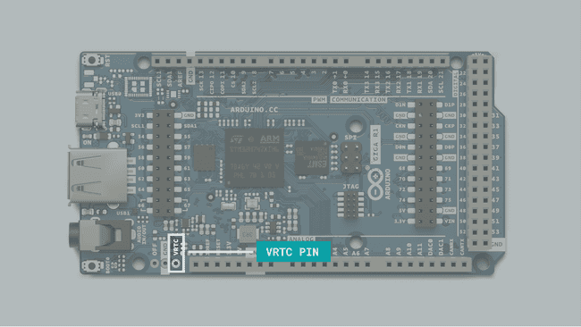
Camera Interface
The Arduino GIGA features an onboard Arducam compatible connector.
To learn more about the camera capabilities of the GIGA R1, check out the GIGA R1 Camera Guide
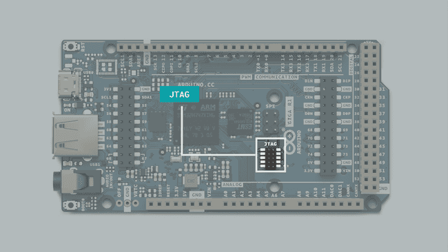
JTAG
The GIGA R1 features a 2x5 pin JTAG (Joint Test Action Group) connector, giving advanced debug functionalities for more advanced users.
CAN Bus
The GIGA R1 features a dedicated CAN bus.
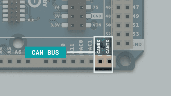
The CAN bus does not include a built in transceiver. If you need to use the CAN bus, you can add a transceiver as a breakout board.
CAN, or Controller Area Network, is a communication standard that allows microcontroller-based devices to communicate with each other without the need for a host computer. This means that building a complex system with many different subsystems within becomes much easier.
This makes the GIGA R1 a powerful option for complex multilayered systems, as it can be integrated into existing systems or be used to build a new one from scratch.
The CAN pins on the GIGA R1 are labelled
CANRXCANTX| GIGA R1 | Transceiver |
|---|---|
| VCC | 3.3V |
| GND | GND |
| CANTX | CANTX* |
| CANRX | CANRX* |
*The name of CANTX/CANRX differs from product to product.
Below is an example of how to send & receive data using a CAN bus.
1#include "CAN.h"2
3mbed::CAN can1(PB_5, PB_13);4uint8_t counter = 0;5
6void send() {7 Serial.println("send()");8 if (can1.write(mbed::CANMessage(1337, &counter, 1))) {9 Serial.println("wloop()");10 counter++;11 Serial.print("Message sent: ");12 Serial.println(counter);13 } else {14 Serial.println("Transmission error");15 Serial.println(can1.tderror());16 can1.reset();17 }18}19
20void receive() {21 mbed::CANMessage msg;22 if (can1.read(msg)) {23 Serial.print("Message received: ");24 Serial.println(msg.data[0]);25 }26}27
28
29void setup() {30 Serial.begin(115200);31 can1.frequency(1000000);32}33
34bool receiver = false;35void loop() {36 if (receiver) {37 receive();38 } else {39 send();40 }41 delay(1000);42}SPI
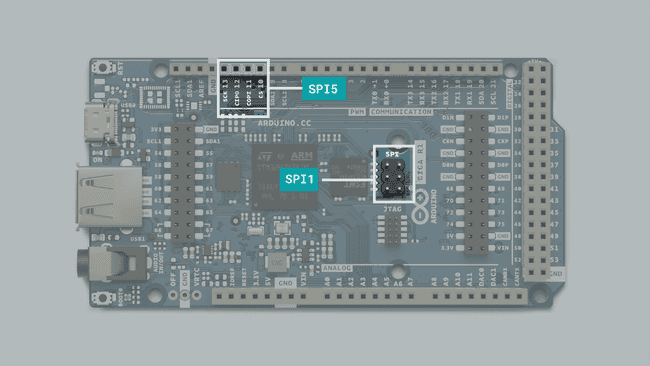
The GIGA R1 features two separate SPI (Serial Peripheral Interface) buses, one is configured on the 6 pin header (ICSP) labelled SPI, and the other is broken out into pin connections on the board.
The first bus which has a dedicated SPI header,
SPI1- (CIPO) - D89
- (COPI) - D90
- (SCK) - D91
- (CS) - unassigned, use any free GPIO for this.
Please note that the SPI header provides a 5 V pin. Make sure that the SPI device you are connecting supports an input voltage of 5 V. If you have an SPI device that supports 3.3 V only, use the
port (see below).SPI5
The second bus (header),
SPI5- (CIPO) - D12
- (COPI) - D11
- (SCK) - D13
- (CS) - D10
For using both SPI buses simultaneously, check out the following example:
1#include <SPI.h>2
3const int CS_1 = 10;4const int CS_2 = 5;5
6void setup() {7 pinMode(CS_1, OUTPUT);8 pinMode(CS_2, OUTPUT);9
10 SPI.begin();11 SPI1.begin();12
13 digitalWrite(CS_1, LOW);14 digitalWrite(CS_2, LOW);15
16 SPI.transfer(0x00);17 SPI1.transfer(0x00);18 19 digitalWrite(CS_1, HIGH);20 digitalWrite(CS_2, HIGH);21}22
23void loop() {24}Please note that the in the GIGA R1 schematics and the code does not match exactly. In the schematics, you will notice that
SPISPI1SPI1SPI5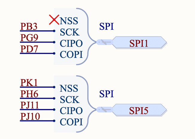
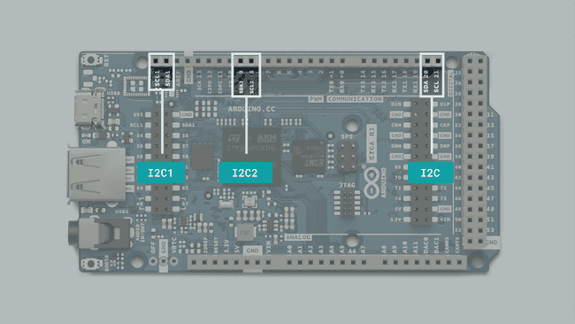
I2C Pins
I2C lets you connect multiple I2C compatible devices in series using only two pins. The controller will send out information through the I2C bus to a 7 bit address, meaning that the technical limit of I2C devices on a single line is 128. Practically, you're never gonna reach 128 devices before other limitations kick in.
The GIGA R1 has three separate I2C buses of which two are usable without external components, letting you control more devices.
The pins used for I2C on the GIGA R1 are the following:
- SDA - D20
- SCL - D21
- SDA1 - also available on the camera connector.
- SCL1 - also available on the camera connector.
- SDA2 - D9
- SCL2 - D8
To connect I2C devices you will need to include the Wire library at the top of your sketch.
1#include <Wire.h>Inside
void setup()1Wire.begin() //SDA & SDL2Wire1.begin(); //SDA1 & SDL13Wire2.begin(); //SDA2 & SDL2And to write something to a device connected via I2C, we can use the following commands:
1Wire.beginTransmission(1); //begin transmit to device 12Wire.write(byte(0x00)); //send instruction byte 3Wire.write(val); //send a value4Wire.endTransmission(); //stop transmitIf you pay close attention you may notice that there are three sets of I2C pins. The two first sets (SDA, SCL, SDA1, SCL1) have internal pullup resistors connected to them which are required to make them function as I2C pins.
If you want to use the third set (SDA2, SCL2) as I2C pins you will need to use external pull-up resistors.
Serial/UART Pins
The GIGA R1 supports, like every other Arduino board, serial communication with UART (Universal Asynchronous, Receiver-Transmitter). However, the GIGA R1 board features 5 separate serial ports, including the standard serial over USB port that is initialized using
Serial.begin()This not only means that you may print different values to different ports and monitor them separately, which is useful enough in and of itself, but that you may also communicate with 4 different serial enabled devices simultaneously.
The pins used for UART on the GIGA R1 are the following:
- RX0 - D0
- TX0 - D1
- RX1 - D19
- TX1 - D18
- RX2 - 17
- TX2 - 16
- RX3 - 15
- TX3 - 14
Each Serial port works in the same way as the one you're used to, but you use different functions to target them:
1Serial.begin(9600); //initialize serial communication over USB2Serial1.begin(9600); //initialize serial communication on RX0/TX03Serial2.begin(9600); //initialize serial communication on RX1/TX14Serial3.begin(9600); //initialize serial communication on RX2/TX25Serial4.begin(9600); //initialize serial communication on RX3/TX3To send and receive data through UART, we will first need to set the baud rate inside
void setup()1Serial1.begin(9600);To read incoming data, we can use a while loop() to read each individual character and add it to a string.
1while(Serial1.available()){2 delay(2);3 char c = Serial1.read();4 incoming += c;5 }And to write something, we can use the following command:
1Serial1.write("Hello world!");Pins
The GIGA R1 gives you access to more pins than any other Arduino board that is this accessible for makers. Many of them have special features that will be accounted for in the upcoming sections of this article. Keep reading to learn what you can do with them.
If you just need a quick overview of the pins functionality, this is a full table of all the IO pins on the GIGA R1
| Pin | Function | Notes |
|---|---|---|
| 0 | TX | Serial communication |
| 1 | RX | Serial communication |
| 2 | PWM | PWM, Digital IO pin |
| 3 | PWM | PWM, Digital IO pin |
| 4 | PWM | PWM, Digital IO pin |
| 5 | PWM | PWM, Digital IO pin |
| 6 | PWM | PWM, Digital IO pin |
| 7 | PWM | PWM, Digital IO pin |
| 8 | PWM/SCL2 | PWM, Digital IO, I2C |
| 9 | PWM/SDA2 | PWM, Digital IO, I2C |
| 10 | PWM/CS | PWM, Digital IO, SPI |
| 11 | PWM/COPI | PWM, Digital IO, SPI |
| 12 | PWM/CIPO | PWM, Digital IO, SPI |
| 13 | PWM/SCK | PWM, Digital IO, SPI |
| 14 | TX3 | Serial communication |
| 15 | RX3 | Serial communication |
| 16 | TX2 | Serial communication |
| 17 | RX2 | Serial communication |
| 18 | TX1 | Serial communication |
| 19 | RX1 | Serial communication |
| 20 | SDA | Digital IO, I2C |
| 21 | SCL | Digital IO, I2C |
| 22 | GPIO | Digital IO pin |
| 23 | GPIO | Digital IO pin |
| 24 | GPIO | Digital IO pin |
| 25 | GPIO | Digital IO pin |
| 26 | GPIO | Digital IO pin |
| 27 | GPIO | Digital IO pin |
| 28 | GPIO | Digital IO pin |
| 29 | GPIO | Digital IO pin |
| 30 | GPIO | Digital IO pin |
| 31 | GPIO | Digital IO pin |
| 32 | GPIO | Digital IO pin |
| 33 | GPIO | Digital IO pin |
| 34 | GPIO | Digital IO pin |
| 35 | GPIO | Digital IO pin |
| 36 | GPIO | Digital IO pin |
| 37 | GPIO | Digital IO pin |
| 38 | GPIO | Digital IO pin |
| 39 | GPIO | Digital IO pin |
| 40 | GPIO | Digital IO pin |
| 41 | GPIO | Digital IO pin |
| 42 | GPIO | Digital IO pin |
| 43 | GPIO | Digital IO pin |
| 44 | GPIO | Digital IO pin |
| 45 | GPIO | Digital IO pin |
| 46 | GPIO | Digital IO pin |
| 47 | GPIO | Digital IO pin |
| 48 | GPIO | Digital IO pin |
| 49 | GPIO | Digital IO pin |
| 50 | GPIO | Digital IO pin |
| 51 | GPIO | Digital IO pin |
| 52 | GPIO | Digital IO pin |
| 53 | GPIO | Digital IO pin |
| 54 | GPIO | Digital IO pin |
| 55 | GPIO | Digital IO pin |
| 56 | GPIO | Digital IO pin |
| 57 | GPIO | Digital IO pin |
| 58 | GPIO | Digital IO pin |
| 59 | GPIO | Digital IO pin |
| 60 | GPIO | Digital IO pin |
| 61 | GPIO | Digital IO pin |
| 62 | GPIO | Digital IO pin |
| 63 | GPIO | Digital IO pin |
| 64 | GPIO | Digital IO pin |
| 65 | GPIO | Digital IO pin |
| 66 | GPIO | Digital IO pin |
| 67 | GPIO | Digital IO pin |
| 68 | GPIO | Digital IO pin |
| 69 | GPIO | Digital IO pin |
| 70 | GPIO | Digital IO pin |
| 71 | GPIO | Digital IO pin |
| 72 | GPIO | Digital IO pin |
| 73 | GPIO | Digital IO pin |
| 74 | GPIO | Digital IO pin |
| 75 | GPIO | Digital IO pin |
| A0 | Analog in | Analog In |
| A1 | Analog in | Analog In |
| A2 | Analog in | Analog In |
| A3 | Analog in | Analog In |
| A4 | Analog in | Analog In |
| A5 | Analog in | Analog In |
| A6 | Analog in | Analog In |
| A7 | Analog in | Analog In |
| A8 | Analog in | Analog In |
| A9 | Analog in | Analog In |
| A10 | Analog in | Analog In |
| A11 | Analog in | Analog In |
| A12 | DAC0 | Analog In, DAC |
| A13 | DAC1 | Analog In, DAC |
| A14 | CANRX | Analog In, CAN |
| A15 | CANTX | Analog In, CAN |
Analog Pins
The GIGA R1 has 12 analog input pins that can be read with a resolution of 16 Bits, by using the
analogRead()1value = analogRead(pin, value);The reference voltage of these pins is 3.3V.
Pins A8, A9, A10 and A11 can not be used as GPIOs, but are limited to use as analog input pins.
The STM32H7 has an internal OPAMP and comparator that are exposed on the GIGA R1 as follows:
| Pin | OPAMP | Comparator |
|---|---|---|
| A0 | OPAMP1_VOUT | COMP1_INM |
| A1 | OPAMP1_VINM &VINM0 | |
| A2 | OPAMP1_VINP | COMP1_INP |
| A3 | COMP1_INM | |
| A6 | COMP1_INM |
For more advanced analog readings, you can use the
library. Read more about this in the Advanced ADC section.AdvancedAnalogRedux
PWM Pins
PWM (Pulse Width Modulation) capability allows a digital pin to emulate analog output by flickering on and off very fast letting you, among other things, dim LEDs connected to digital pins.
The GIGA R1 has 12 PWM capable pins, the PWM capable pins are 2-13. You may use them as analog output pins with the function:
1analogWrite(pin, value);Digital Pins
The GIGA R1 features more pins than any other Arduino board for makers, a full 76 digital pins. Though many of them serve another purpose and shouldn't be used for GPIO if you have other pins available.
- 0 - RX0
- 1 - TX0
- 8 - SCL2
- 9 - SDA2
- 10 - CS
- 11 - COPI
- 12 - CIPO
- 13 - SCK
- 14 - TX3
- 15 - RX3
- 16 - TX2
- 17 - RX2
- 18 - TX1
- 19 - RX1
- 20 - SDA
- 21 - SCL
The reference voltage of all digital pins is 3.3V.
The logic for
LED_BUILTINLED_BUILTIND7 Pin
By default, the digital pin 7 (D7) provides a voltage of ~1.65 V.
To disable this pin, you need to configure it as an output and set it to a
LOW1pinMode(7, OUTPUT);2digitalWrite(7, LOW);DAC Pins
The GIGA R1 also has two DAC pins, A12 & A13, that can act as genuine analog output pins which means they are even more capable than PWM pins.
1analogWrite(pin, value);
These DAC pins have a default write resolution of 8-bits. This means that values that are written to the pin should be between 0-255.
However you may change this write resolution if you need to, to up to 12-bits:
1analogWriteResolution(12);For advanced usage of the DAC, you can use the
library. Read more about this in the Advanced DAC section.AdvancedAnalogRedux
OFF Pin
On the GIGA R1 you will find a pin labelled "OFF". If you connect this pin to ground, the board will power down even if power is supplied to the board.
You can install a flip-switch to the board to let you turn your device on and off easily, which can be a handy option for a more permanent fixture.
Interrupts
If you're creating a project that relies heavily on accurate sensor data, and therefore need to ensure that you read the record any change in value, it can be difficult to write a program that does anything else well. This is because the microcontroller is busy trying to read the values constantly. To get around this you can use interrupts that can let you can be useful for reading input from for example a rotary encoder or a push button without putting any code in your loop function.
This feature might be extra valuable to the maker with an GIGA R1, as their circuit gets more and more complex.
All GPIO pins on the GIGA R1 can be used for interrupts.
The syntax for creating an interrupt function should be included in
void setup()1attachInterrupt(digitalPinToInterrupt(pin), ISR, mode)
represents the pin number of the pin your input sensor is connected to,pin
is the function that is called whenever the interrupt is triggered, and should be defined bt you somewhere in your sketch.ISR
defines when the interrupt should be triggered, and can be one of four pre-defined modes.mode
The different modes that can be used are:
triggers the interrupt when the pin is low.LOW
triggers whenever the pin changes values.CHANGE
triggers when the pin goes from low to high.RISING
triggers when the pin goes from high to low.FALLING
This example sketch will turn on or off an LED connected to pin 13 whenever a pushbutton connected to pin 2 is pressed or released:
1const byte ledPin = 13;2const byte interruptPin = 2;3volatile byte state = LOW;4
5void setup() {6 pinMode(ledPin, OUTPUT);7 pinMode(interruptPin, INPUT_PULLUP);8 attachInterrupt(digitalPinToInterrupt(interruptPin), blink, CHANGE);9}10
11void loop() {12 digitalWrite(ledPin, state);13}14
15void blink() {16 state = !state;17}Suggest changes
The content on docs.arduino.cc is facilitated through a public GitHub repository. If you see anything wrong, you can edit this page here.
License
The Arduino documentation is licensed under the Creative Commons Attribution-Share Alike 4.0 license.