Getting Started with the GIGA Display Shield
Learn how to set up and use the GIGA Display Shield and get an overview of its features.
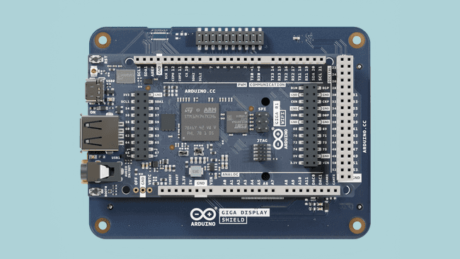
The GIGA Display Shield is an accessory shield designed for the GIGA R1 WiFi board. With it, you can render fast & sophisticated user interfaces on a 800x480 display with touch support.
In this guide you will learn how to set your board up with the GIGA R1 WiFi board & become familiar with the available libraries to control it.
Hardware & Software Needed
Overview
To use the GIGA Display Shield, there are currently three supported alternatives to draw on the display.
Option 1: GFX Library
The Arduino_GigaDisplay_GFX library is a layer library for the Adafruit_GFX graphic core library. This library makes it easy to draw geometrical shapes, printing values, drawing pixels and more.
To get started with the GFX library, visit the GIGA Display Shield GFX Guide.
Option 2: LVGL
The LVGL framework supports building more advanced UIs with dropdown menus, interactive buttons, scroll functionality using a grid system.
To get started, visit the GIGA Display LVGL Guide.
Option 3: ArduinoGraphics
ArduinoGraphics is a simple library for more primitive drawings with a similar API to the GFX library.
To get started, visit the GIGA Display Shield Draw Images Guide.
Board Package & Libraries
The GIGA Display Shield requires you to install the Board Package for GIGA boards, along with some additional software libraries.
The libraries can be installed via the Arduino IDE's library manager, where you will also discover examples.
GIGA Board Package
To use the shield you will need a GIGA R1 WiFi board. You also need to install the GIGA Board Package, which can be done directly in the Arduino IDE, under "Board Manager". The source code for this Board Package can be found in this GitHub repository.
For more details, see Getting Started with GIGA R1 WiFi.
Arduino_H7_Video
The Arduino_H7_Video manages the video output and integrates third party frameworks such as LVGL. This library is used to configure and initialize the display and to perform basic draw functions.
This library is included with the GIGA Board Package, and does not need to be installed. The documentation for this library is available here.
ArduinoGraphics
The ArduinoGraphics is required for drawing operations on the screen.
For source code and issues with the ArduinoGraphics library, please see the GitHub repository.
Arduino_GigaDisplayTouch
The Arduino_GigaDisplayTouch is required for reading touch points on the screen, and is needed when using the LVGL's framework.
For source code and issues with the Arduino_GigaDisplayTouch library, please see the GitHub repository.
Arduino_GigaDisplay_GFX
The Arduino_GigaDisplay_GFX library is a layer library for the Adafruit_GFX graphics core library.
This library is great for drawing geometrical shapes, printing text & values, drawing pixels and so on. It is recommended for beginners.
Learn more about this library in the GIGA Display Shield GFX Guide.
Arduino_GigaDisplay
The Arduino_GigaDisplay provides a large set of examples that can be used with the shield, many of which are included in the guides found in the documentation.
This library is also required to use the built-in RGB, which you can read more about in the RGB section.
This library lists out all recommended libraries as dependencies. Installing it through the IDE will also prompt you to install the libraries listed above.
Arduino_BMI270_BMM150 (IMU)
To access the onboard IMU, use the Arduino_BMI270_BMM150 library.
You can read more about its methods in the library documentation.
More information available in the IMU section in this document.
Hardware Setup
To use the GIGA Display Shield, mount it on the bottom side of the GIGA R1 WiFi board. The GIGA R1 WiFi board will be flipped upside down when the display is used.

This makes it possible to freely use the GIGA R1 WiFi's pins while the display shield is connected.
Camera Connector
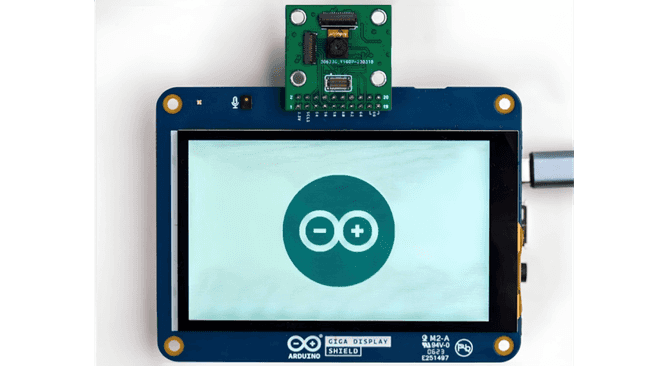
Located on the top side of the shield is a 20 pin camera connector, which is Arducam® compatible and supports a wide range of cameras. The connector is connected to the GIGA R1 WiFi's camera connector, and is compatible with a wide range of cameras (see Arducam cameras).
The camera can only be mounted on the front of the display shield, meaning it only works in selfie mode. Do not attempt to connect the camera from the back. See the image below for how to connect it:

Read more about this in the GIGA Display Camera Connector Guide, complete with an example.
IMU
This shield has a built-in IMU module, the BMI270. This sensor can be used for a number of purposes, for example to automatically orientate an object on the screen, see the following tutorial:
To access BMI270, use the BMI270-250 library. Please note that the sensor is not connected to the main I2C bus, so you will need to initialize the sensor on another bus. To do so, simply add the line below to the top of your sketch:
1BoschSensorClass imu(Wire1);Note that the examples use the default
IMU1IMU.begin() //for other boards2imu.begin() //for GIGA Display ShieldGyroscope
The below example can be used to access the gyroscope data:
1#include "Arduino_BMI270_BMM150.h"2BoschSensorClass imu(Wire1);3
4void setup() {5 Serial.begin(9600);6 while (!Serial);7 Serial.println("Started");8
9 if (!imu.begin()) {10 Serial.println("Failed to initialize imu!");11 while (1);12 }13 Serial.print("Gyroscope sample rate = ");14 Serial.print(imu.gyroscopeSampleRate());15 Serial.println(" Hz");16 Serial.println();17 Serial.println("Gyroscope in degrees/second");18 Serial.println("X\tY\tZ");19}20
21void loop() {22 float x, y, z;23
24 if (imu.gyroscopeAvailable()) {25 imu.readGyroscope(x, y, z);26
27 Serial.print(x);28 Serial.print('\t');29 Serial.print(y);30 Serial.print('\t');31 Serial.println(z);32 }33}Accelerometer
The below example can be used to access the accelerometer data:
1#include "Arduino_BMI270_BMM150.h"2BoschSensorClass imu(Wire1);3
4void setup() {5 Serial.begin(9600);6 while (!Serial);7 Serial.println("Started");8
9 if (!imu.begin()) {10 Serial.println("Failed to initialize imu!");11 while (1);12 }13
14 Serial.print("Accelerometer sample rate = ");15 Serial.print(imu.accelerationSampleRate());16 Serial.println(" Hz");17 Serial.println();18 Serial.println("Acceleration in G's");19 Serial.println("X\tY\tZ");20}21
22void loop() {23 float x, y, z;24
25 if (imu.accelerationAvailable()) {26 imu.readAcceleration(x, y, z);27
28 Serial.print(x);29 Serial.print('\t');30 Serial.print(y);31 Serial.print('\t');32 Serial.println(z);33 }34}Microphone
This shield has an embedded omnidirectional microphone, MP34DT06JTR, which can be used together with the PDM library. This library is shipped with the GIGA Board Package, so there's no need to manually install it.
Below is a minimal sketch that will print out the samples in the serial plotter (See Using the Serial Plotter Tool for more information).
1#include <PDM.h>2
3// default number of output channels4static const char channels = 1;5
6// default PCM output frequency7static const int frequency = 16000;8
9// Buffer to read samples into, each sample is 16-bits10short sampleBuffer[512];11
12// Number of audio samples read13volatile int samplesRead;14
15void setup() {16 Serial.begin(9600);17 while (!Serial);18
19 // Configure the data receive callback20 PDM.onReceive(onPDMdata);21
22 // Optionally set the gain23 // Defaults to 20 on the BLE Sense and 24 on the Portenta Vision Shield24 // PDM.setGain(30);25
26 // Initialize PDM with:27 // - one channel (mono mode)28 // - a 16 kHz sample rate for the Arduino Nano 33 BLE Sense29 // - a 32 kHz or 64 kHz sample rate for the Arduino Portenta Vision Shield30 if (!PDM.begin(channels, frequency)) {31 Serial.println("Failed to start PDM!");32 while (1);33 }34}35
36void loop() {37 // Wait for samples to be read38 if (samplesRead) {39
40 // Print samples to the serial monitor or plotter41 for (int i = 0; i < samplesRead; i++) {42 if(channels == 2) {43 Serial.print("L:");44 Serial.print(sampleBuffer[i]);45 Serial.print(" R:");46 i++;47 }48 Serial.println(sampleBuffer[i]);49 }50
51 // Clear the read count52 samplesRead = 0;53 }54}55
56/**57 * Callback function to process the data from the PDM microphone.58 * NOTE: This callback is executed as part of an ISR.59 * Therefore using `Serial` to print messages inside this function isn't supported.60 * */61void onPDMdata() {62 // Query the number of available bytes63 int bytesAvailable = PDM.available();64
65 // Read into the sample buffer66 PDM.read(sampleBuffer, bytesAvailable);67
68 // 16-bit, 2 bytes per sample69 samplesRead = bytesAvailable / 2;70}To get started with the microphone, visit the GIGA Display Shield Microphone Guide.
RGB
This shield has a built in RGB pixel that is controlled via I2C. To use this, install the Arduino_GigaDisplay library. The following sketch is a minimal example that will blink the blue pixel every second.
1#include <Arduino_GigaDisplay.h>2
3GigaDisplayRGB rgb; //create rgb object4
5void setup() {6 rgb.begin(); //init the library7}8
9void loop() {10 rgb.on(0, 0, 255); //turn on blue pixel11 delay(1000);12 rgb.off(); //turn off all pixels13 delay(1000);14}Power Consumption
The following test results were recorded with some sample sketches. The setup consist of a GIGA R1 WiFi and a GIGA Display Shield mounted, using the following equipment & software:
| Sketch | Min | Max | Average |
|---|---|---|---|
| GFX | 327.20 mA | 382.15 mA | 363.50 mA |
| LVGL | 294.90 mA | 412.49 mA | 347.97 mA |
Links to the sketches used for these tests are found below:
When selecting an appropriate power source (battery), use the measurements above as guidelines. For example, running one of the above sketches with a 1000 mAh battery will only last approx. 2 hours.
Note that there are other factors at play, such as the battery's discharge rate and the general quality of the battery. The above formulas and measurements are to be considered guidelines, please consult the technical information of your battery for more accurate results.
Suggest changes
The content on docs.arduino.cc is facilitated through a public GitHub repository. If you see anything wrong, you can edit this page here.
License
The Arduino documentation is licensed under the Creative Commons Attribution-Share Alike 4.0 license.