Arduino PLC IDE Pin Mapping
Assign the pins to variables and interact with them on the Arduino PLC IDE.
Introduction
In this tutorial you will see how to access the available pins of your device as variables, you will create a Pin Map Table, configure it and interact with the pins from your PLC programs.
What Is A Map Table
A mapping table is a table that links a source, like the memory address of an I/O, and its target name which functions as an alias. For example, if a microcontroller has an I/O with the name
PA01digitalOut01If you are familiar with the C languages, it is similar to the way a pointer works.
Using mapping tables makes your programs easier to read, which is always a good practice for long-term maintenance.
Required Hardware and Software
- Portenta Machine Control
- Arduino PLC IDE
- 24V DC power source (Needed to supply the Digital Output pins)
Remember to connect the 24V input on the device to see the status LEDs of the digital outputs. The LEDs indicate if the output is HIGH, which means it is delivering out power. If you do not connect the 24V DC Supply you will not be able to see the state of the pins, as they are being controlled by the microcontroller but they are not delivering power.
Create a New Project
First of all, open the Arduino PLC IDE and create a new project (or open an existing one).

Create Map Tables
Resources Tab
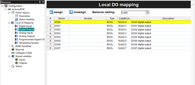
Navigate to the Resources tile window and you will see a list of the available mappings for your device. In the case of the Portenta Machine Control you have:
- Digital Inputs
- Digital Outputs
- Analog Inputs
- Analog Outputs
- Programmable Digital I/O
- Temperature Probes

Table (Pin Map)
Each element of the table contains the Variable cell to define a variable in which the data or status of the pin is going to be stored.

Assign New Variables
To create a variable for a pin map you have two options:
- Create a single variable for a single pin
- Create a bool array to contain multiple pins
By default they are not available as variables, in any case, you can get the values by accessing their memory registers, which is not as easy as having variables with the data.
Single Variable
Double-click the Pin Map that you want to edit, for example, the Digital Output table.
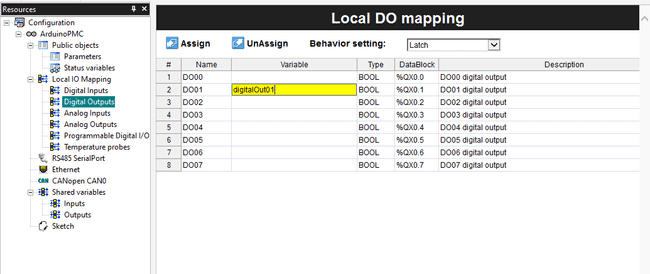
To assign a new variable you can type the name on the variable column, if it is new it will be automatically created if it exists it will change its value to the pin's state.
We will assign to the Digital Output pin 2 the name digitalOut01

To interact with the digital output pin you can use this code:
1// Set the Digital Output 01 to HIGH2
3digitalOut01 := 1;Array
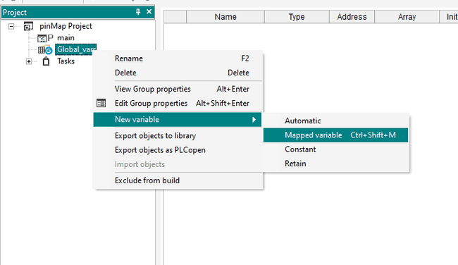
Go to your project tile window, and right-click on the Global Variable element.
Navigate to New Variable > Mapped Variable.

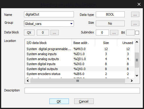
Now on the popup menu, you can set the name of the variable, then select the type of pins that are going to contain scroll on the Location section, and you will see several types of pins, we will select the System Digital OUTPUTS and name it as
.digitalOut


As it is an array you will be able to access its pin in a For loop like the following:
1// Set all the Digital Outputs to HIGH2
3FOR pinNumber := 0 TO 7 DO4 digitalOut[pinNumber] := 1;5END_FOR;Next Steps
Now that you've learned how to assign Pin Maps, you could:
- Make a blink program with the digital outputs
- Map the temperature probes pins and get the temperature of your environment
Troubleshooting
- If you do not see the LED of the digital output channel change when you follow this tutorial, make sure you have connected the power supply with 24V DC on the 24V Input pins
Suggest changes
The content on docs.arduino.cc is facilitated through a public GitHub repository. If you see anything wrong, you can edit this page here.
License
The Arduino documentation is licensed under the Creative Commons Attribution-Share Alike 4.0 license.