MKR IoT Carrier Rev2 Cheat Sheet
Learn how to set up the MKR IoT Carrier Rev2, get a quick overview of the compatible boards, components, and the library.
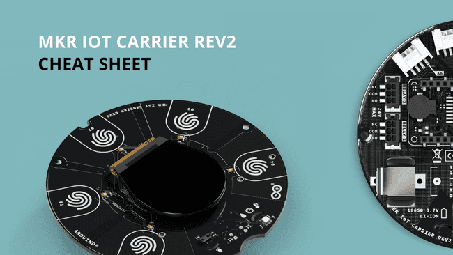
The Arduino® MKR IoT Carrier Rev2 is equipped with different sensors, actuators and with a display to leave you free to focus on prototyping and programming your next IoT projects. The carrier does not come equipped with a microcontroller, meaning it only works in combination with an Arduino board. The MKR IoT Carrier Rev2 comes equipped with 5 RGB LEDs, 5 capacitive touch buttons, a colored display, IMU and a variety of quality sensors. It also features a battery holder for a 18650 Li-Ion battery, SD card holder and Grove connectors.
Compatible Boards
The MKR family of boards share a common pinout, meaning that they can all be easily connected to the MKR IoT Carrier Rev2. Here is a list of the MKR boards:
- MKR 1000 WiFi
- MKR FOX 1200
- MKR GSM 1400
- MKR NB 1500
- MKR Vidor 4000
- MKR WAN 1300
- MKR WAN 1310
- MKR WiFi 1010
- MKR Zero
The MKR family boards offer different features that can be useful for your projects. You can browse through the boards and pick the one that is most compatible for your project.
Assembly
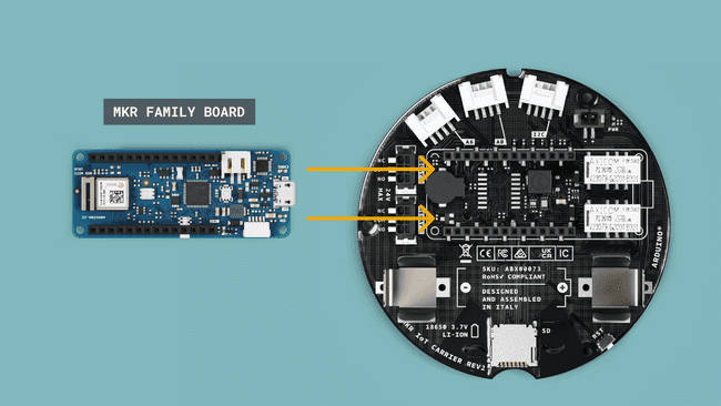
The chosen Arduino MKR board needs to be mounted on top of the MKR IoT Carrier Rev2 and connected to a computer. The board can be connected as shown in the image below, matching the pin numbers on the board to the ones on the carrier.
Datasheet
The full datasheet is available as a downloadable PDF from the link below:
Arduino Cloud
The MKR IoT Carrier Rev2 can be controlled through the Arduino Cloud, a Cloud service that allows us to create IoT applications in just minutes, if combined with an Arduino Cloud compatible board. Here's a list of the Arduino MKR family boards that are compatible with the Arduino Cloud:
Note: The MKR GSM 1400 and MKR NB 1500 require a SIM card to connect to the Cloud, as they communicate over the mobile networks. The MKR WAN 1300 and 1310 board requires a Arduino PRO Gateway LoRa® to connect to the Cloud.
If you need help to get started, you can go through the Arduino Cloud tutorial.
Pinout
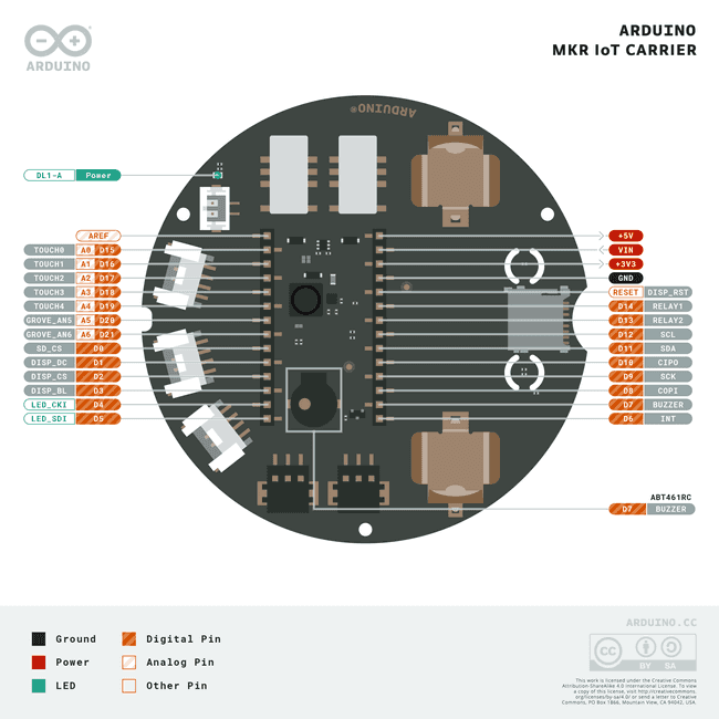
The full pinout is available in the resources section.
Grove Connectors
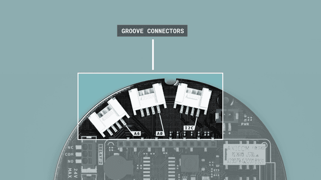
The MKR IoT Carrier Rev2 comes with three grove connectors (2 analog and 1 I2C) that enables us to easily connect external sensors. The type of the connector is labeled clearly on the back of the carrier.
Carrier Library
To program the MKR IoT Carrier Rev2, the Arduino_MKRIoTCarrier library needs to be included. This library allows us to control and read all the components of the MKR IoT Carrier Rev2. Setting up the Arduino_MKRIoTCarrier library requires an addition of few code lines in the initialization and setup. Practically speaking, the code used in the initialization and setup is rarely changed, and it is required in every sketch.
Initialization
In the initialization (the very top) of every sketch, the Arduino_MKRIoTCarrier library needs to be included, which includes the individual libraries of the components mounted onto the carrier.
Next, an object of type
MKRIoTCarriercarrier1#include <Arduino_MKRIoTCarrier.h>2MKRIoTCarrier carrier;Setup
Inside the
setup()First, we need to tell the library whether the carrier is being used inside the plastic enclosure included in the Oplà IoT Kit or not. The library uses this information in order to calibrate the sensitivity of the capacitive buttons.
If you use the plastic enclosure, add this line:
1carrier.withCase();Otherwise, add this line:
1carrier.noCase();After that, the
carrier.begin();1void setup() {2 carrier.noCase();3 carrier.begin();4}BME688 Environmental Sensor
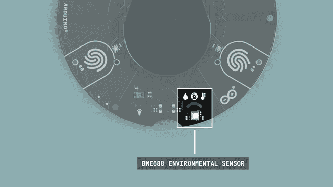
The BME688 Environmental Sensor is a 4 in 1 sensor capable of providing the following measurements:
- Humidity, 0‒100% r.H.
- Temperature, -40 to +85 °C.
- Pressure, 300-1100 hPa.
- Gas, IAQ, VOC, CO2.
BME688 is a low-power sensor with current consumption as low as 2.1 µA at 1 Hz. It communicates over the I²C bus as other sensors onboard this carrier.
Code
The values from the temperature, humidity & pressure can be retrieved and stored in float variables as shown below. For this, we need to use the
Env1float temperature = carrier.Env.readTemperature();2float temperature = carrier.Env.readTemperature(FAHRENHEIT);3float humidity = carrier.Env.readHumidity();4float pressure = carrier.Env.readPressure(); //returns value in kPaTemperature is returned in degrees Celsius, while relative humidity is returned in percentage.
To access gas various values, we need to use the
AirQuality1float gasResistor = carrier.AirQuality.readGasResistor();2float volatileOrganicCompounds = carrier.AirQuality.readVOC();3float co2 = carrier.AirQuality.readCO2();IMU Accelerometer & Gyroscope Sensors
The IMU (Inertial Measurement Unit) used on the MKR IoT Carrier Rev2 is the located behind the display.
LSM6DSOX
The LSM6DSOX from STM is an IMU (Inertial Measurement Unit) that features a 3D digital accelerometer and a 3D digital gyroscope.
Code
The 3-axis values from the accelerometer and gyroscope sensors can be retrieved and stored in float variables as shown below:
1float x, y, z;2
3void loop(){4 if (carrier.IMUmodule.accelerationAvailable())5 {6 carrier.IMUmodule.readAcceleration(x, y, z);7 Serial.println(x);8 }9}The following methods can be used to detect movement:
1carrier.IMUmodule.accelerationAvailable();Returns 0 if no new acceleration data sample is available, 1 if new acceleration data sample is available.
1carrier.IMUmodule.readAcceleration(x, y, z);Reads acceleration data from the sensor on the three axis and assigns it to the provided variables.
The underlying library used to read the sensor is LSM6DSOX.
RGB and Gesture Sensor
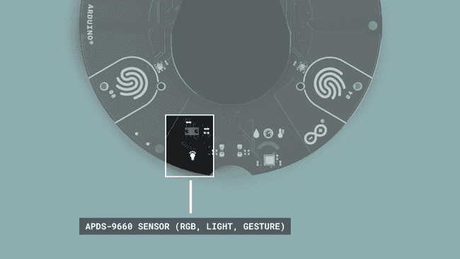
The MKR IoT Carrier Rev2 contains a Broadcom APDS-9960 RGB and Gesture sensors, situated under the display and marked with a bulb icon. The sensor is useful for ambient light and RGB color sensing, proximity sensing, and gesture detection.
Code
The color values from the RGB sensor can be retrieved and stored in int variables as shown below.
The
carrier.Light.readColor(r, g, b);The if statement
if (r >= 135 && g >= 135 && b >= 135)1int r, g, b;2
3 void loop(){4
5 if (carrier.Light.colorAvailable()){6 carrier.Light.readColor(r, g, b); //read rgb color values7
8 // check if color/light is bright enough9 if (r >= 135 && g >= 135 && b >= 135){10 Serial.print("White color detected");11 }12 }13 }The following methods can be used to detect gesture:
1carrier.Light.gestureAvailable();Checks the availability of the gesture sensor.
1carrier.Light.readGesture();Confirms which gesture is being detected, and returns UP, DOWN, RIGHT or LEFT.
The code example below shows the gesture value in a fixed width integer
uint8_tif (gesture == UP)1void loop(){2
3 if (carrier.Light.gestureAvailable())4 {5 uint8_t gesture = carrier.Light.readGesture(); // a variable to store the type of gesture read by the light sensor6 Serial.print("Gesture: ");7
8 // when gesture is UP9 if (gesture == UP)10 {11 Serial.println("UP");12 }13 }The underlying library used to read the sensor is Arduino_APDS9960.
Relays
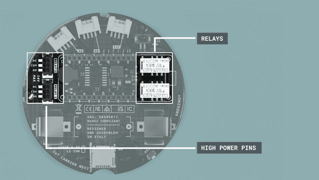
The MKR IoT Carrier Rev2 is equipped with two 5V Coil voltage KEMET EE2-5NU-L relays, located on the back side of the carrier. The relays are non-latching with a COM (common), NO (Normally open) and NC (normally closed) contacts, and can take up a max of 2A Current and 24 V of input each.
The connections between a high power circuit and the relays will be done through these connectors (marked "high power pins" in the image above).
Once the cables are introduced inside the connectors, they will automatically be locked inside. To unlock a cable and remove it from the connector, a tool is needed to be inserted through the top square hole (it can be a flat screwdriver, a hard piece of plastic, etc.).
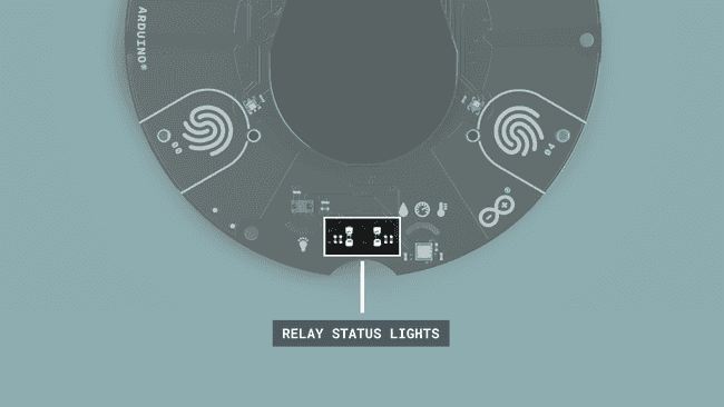
The L1 and L2 LEDs on the carrier are visual indicators of the state of the relays. If the LED is ON, it means that the COM and the NO terminal of the relay are connected, and if the LED is OFF it means that COM and NC are connected.
Code
The
carrier.RelayX.open();carrier.RelayX.close();carrier.RelayX.getStatus();Swap to the Normally Open (NO) circuit of relay 1 (turns it on):
1carrier.Relay1.open();Swap to the Normally Closed (NC) circuit of relay 2 (turns it off), default mode on power off:
1carrier.Relay2.close();Bool, returns the status LOW means NC and HIGH means NO:
1carrier.Relay2.getStatus();Peripherals
Display

The screen on the MKR IoT Carrier Rev2 is a rounded 1.3” TFT display, with a 240 x 240 resolution and a diameter of 36 x 40 mm.
Code
The display is controlled through the
carrier.displayTo get started, check the Adafruit_GFX documentation and see the examples included in the Arduino_MKTIoTCarrier library.
](https://www.arduino.cc/reference/en/libraries/adafruit-st7735-and-st7789-library/), which is included in the carrier's library, meaning that it does not need to be added it separately.
We'll list here some of the most useful methods to configure the MKR IoT Carrier Rev2's display, including basic configurations, background and text colors, font size, position of the cursor and a loading animation.
1carrier.display.fillScreen(color);This method sets the color of the background of the display using hex codes. Example values are:
for white0xFFFF
for black0x0000
for red0xF800
for green0x07E0
for blue0x001F
for cyan0x07FF
for magenta0xF81F
for yellow0xFFE0
for orange0xFC00
1carrier.display.setRotation(0);This method sets the angle of the screen. 0 is the starting position with no rotation.The screen can only be rotated 90, 180 or 270 degrees by replacing the 0 with 1, 2 or 3.
1carrier.display.drawBitmap(x, y, bitmap_visual, w, h, color);This method displays a bitmap visual on the carrier's screen. The values x & y values are the top left coordinates where the visual is drawn, w & h are the width and height of the visual. The data for the bitmap_visual graphic can be stored as a byte array and used as the
bitmap_visual1carrier.display.setTextColor(color);This method sets the color of the text using hex codes.
1carrier.display.setTextSize(number);This method sets the text size. 2 is an average text size since it is visible, but not too small, 3 is a bit larger.
1carrier.display.setCursor(x, y);This method is very important, as it indicates where on the printing starts on the display. It is indicated by pixels, so, if 0, 0 are used for example, it will start printing in the top left corner.
1display.print("text");This method will print the text inside the string at the current cursor position.
More Resources
In order to develop a graphical user interface with the MKR IoT Carrier Rev2, the Arduino_OplaUI library can be used. This library uses the color LEDs, the buzzer and the touch buttons to build an interactive user interface featuring multiple pages. It also includes a few predefined gauges to display values. See the library examples to get started.
Buttons
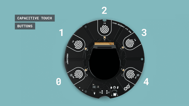
The carrier has five capacitive touch buttons on its top side, numbered from 0 to 4. The buttons are sensitive to direct touch and can also detect wireless touch.
Code
1carrier.Buttons.update();Reads the state of the pads and save them to be used in the different types of touch events.
1carrier.Buttons.getTouch(TOUCH0);Get if the pad is getting touched, true until it gets released.
1carrier.Buttons.onTouchDown(TOUCH0);Get when have been a touch down.
1carrier.Buttons.onTouchUp(TOUCH0);Get when the button has been released.
1carrier.Buttons.onTouchChange(TOUCH0);Get both, touched and released.
Replace
TOUCH0TOUCH1TOUCH2TOUCH3TOUCH41void loop(){2 // updates buttons status3 carrier.Buttons.update();4
5 // Checks if button 00 is touched6 if (carrier.Buttons.onTouchDown(TOUCH0))7 {8 Serial.print("Button 0 pressed down");9 }10 }LEDs
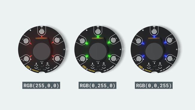
The MKR IoT Carrier Rev2 comes with 5 digital RGB LEDs placed on the top side of the carrier in front of the buttons.
Code
The LEDs are controlled with the Adafruit’s DotStar library, which is included in the
MKRIoTCarrierThe
carrier.leds.show();Here are some of the useful methods used to control the LEDs on the MKR IoT Carrier Rev2:
1carrier.leds.setPixelColor(index, red, green, blue);Sets the color of the index’s LED.
1carrier.leds.setBrightness(255);Set the overall brightness, from 0 (no brightness) to 255 (maximum brightness).
1carrier.leds.clear();Clear the buffer of the LEDs.
1carrier.leds.fill(color, firstLedToCount, count);Fill X amount of the LEDs with the same color.
1uint32_t myColor = carrier.leds.Color(red, green, blue)Saves a custom color.
The code example below shows how to light up all 5 LEDs with our customized color.
1#include <Arduino_MKRIoTCarrier.h>2MKRIoTCarrier carrier;3
4uint32_t myCustomColor = carrier.leds.Color(255,100,50);5
6void setup() {7 carrier.noCase();8 carrier.begin();9 carrier.leds.fill(myCustomColor, 0, 5);10 carrier.leds.show();11}Buzzer
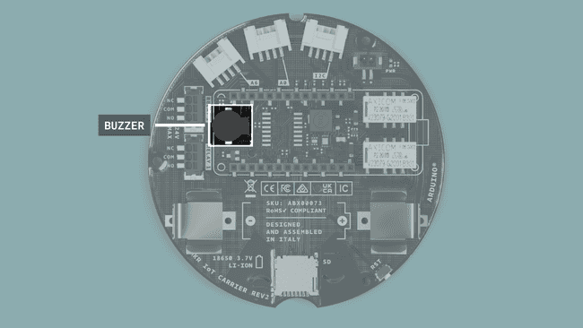
The MKR IoT Carrier Rev2 is equipped with a sound buzzer on the bottom side of the carrier, under the MKR board.
Code
The buzzer can be controlled with the following methods:
1carrier.Buzzer.sound(freq);Equivalent to tone(), it will make the tone with the selected frequency.
1carrier.Buzzer.noSound();Equivalent to noTone(), it will stop the tone signal.
1carrier.Buzzer.beep();2carrier.Buzzer.beep(800, 20);This method is a handy shortcut generating a beep. The two arguments are optional and can be set to customize the frequency and the duration (in milliseconds);
Memory
The MKR IoT Carrier Rev2 contains a SD card slot that accepts a Micro SD.
Code
The memory can be used with the SD library commands that is already included in the
MKRIoTCarrierThe SD class initialized in the main
carrier.begin()1#include <Arduino_MKRIoTCarrier.h>2MKRIoTCarrier carrier;3
4File myFile;5
6void setup() {7 carrier.noCase();8 carrier.begin(); //SD card initialized here9
10 myFile = SD.open("test.txt", FILE_WRITE);11}In order to learn more, check any of the many tutorials about using the
SDPower
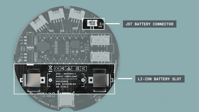
The MKR IoT Carrier Rev2 can be either powered through a USB cable connected to the mounted MKR board, or through a battery. The battery used should be a LI-ION 18650 3.7v battery, which can be mounted to the carrier via the battery holder on the bottom side.
In order to use the USB power to charge the battery, a little cable with JST connectors on both ends is needed between the MKR IoT Carrier Rev2 and the MKR board. The battery can then be recharged via a USB connection through the MKR Board (runs up to 48h with a 3.7v 2500mAh).
Suggest changes
The content on docs.arduino.cc is facilitated through a public GitHub repository. If you see anything wrong, you can edit this page here.
License
The Arduino documentation is licensed under the Creative Commons Attribution-Share Alike 4.0 license.